Chapter 2: Installation
Figure 49. Aligning the AT-SBx31XZ4 XFP Line Card in the Chassis Slot
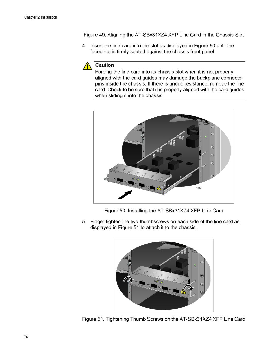
4.Insert the line card into the slot as displayed in Figure 50 until the faceplate is firmly seated against the chassis front panel.
Caution
Forcing the line card into its chassis slot when it is not properly aligned with the card guides may damage the backplane connector pins inside the chassis. If there is undue resistance, remove the line card. Check to be sure that it is properly aligned with the card guides when sliding it into the chassis.
|
|
|
| T |
|
|
|
| E |
|
|
|
| M |
|
|
|
| SBx3161 |
|
|
|
| SBx31FAN |
|
|
|
| 1 |
|
|
|
| POWER |
|
|
|
| 3 |
|
|
|
| 5 |
|
|
|
| 7 |
SBx31XZ4 |
|
|
|
|
0 | PORT | ACTIVITY |
| 9 |
|
| |||
| 10G LINK / | ACT |
| |
1 |
|
|
| |
XFP |
|
| 2 |
|
XFP |
|
|
| 3 |
|
|
| XFP | 1829 |
|
|
|
| |
|
|
|
| XFP |
Figure 50. Installing the AT-SBx31XZ4 XFP Line Card
5.Finger tighten the two thumbscrews on each side of the line card as displayed in Figure 51 to attach it to the chassis.
|
|
|
|
| T |
|
|
|
|
| E |
|
|
|
|
| M |
|
|
|
| SBx3161 |
|
|
|
|
| SBx3 | 1FAN |
|
|
|
|
| |
|
|
|
| 1 |
|
|
|
|
| POWER | |
|
|
|
| 3 |
|
SBx31XZ4 |
|
|
|
|
|
0 | PORT | ACTIVITY |
|
|
|
| 10G | LINK / |
| 5 |
|
1 |
| ACT |
| ||
XFP |
|
|
| 2 |
|
XFP |
|
|
| 3 |
|
|
|
|
| XFP |
|
|
|
|
| XFP |
|
|
|
|
| 7 |
|
|
|
|
| 9 |
|
Figure 51. Tightening Thumb Screws on the AT-SBx31XZ4 XFP Line Card
76