Additional Configuration and Maintenance Tasks
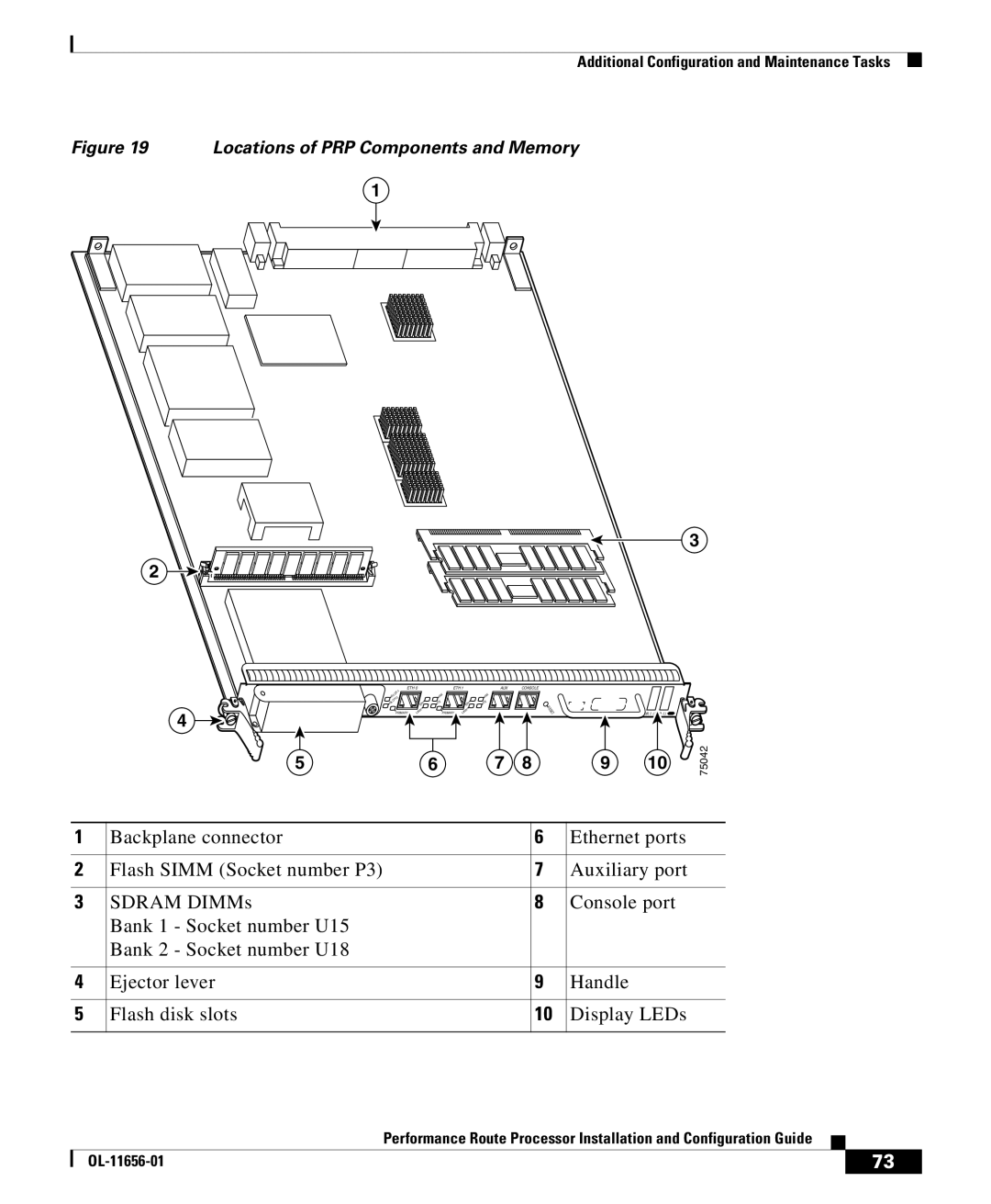
Figure 19 Locations of PRP Components and Memory
1
3
2
4
EJECT
5
ETH 0 | ETH 1 | AUX | CONSOLE |
| ||
|
|
|
|
|
| |
SLO |
| RX |
| RX |
|
|
|
|
|
|
|
| |
SLO | N | TX | N | TX |
|
|
| E |
| E |
| R |
|
| K |
| K |
| E |
|
|
|
| E |
| ||
PRIMARY | LIN | PRIMARY | LIN |
| S | PERFORMANCE ROUTE PROCESSOR 1 |
| T | |||||
6 | 7 | 8 | 9 | 10 | 75042 |
1 | Backplane connector | 6 | Ethernet ports |
|
|
|
|
2 | Flash SIMM (Socket number P3) | 7 | Auxiliary port |
|
|
|
|
3 | SDRAM DIMMs | 8 | Console port |
| Bank 1 - Socket number U15 |
|
|
| Bank 2 - Socket number U18 |
|
|
|
|
|
|
4 | Ejector lever | 9 | Handle |
|
|
|
|
5 | Flash disk slots | 10 | Display LEDs |
|
|
|
|
|
| Performance Route Processor Installation and Configuration Guide |
|
|
|
|
| ||
|
|
| 73 | |
|
|
|