Configuring Interfaces on the PRP
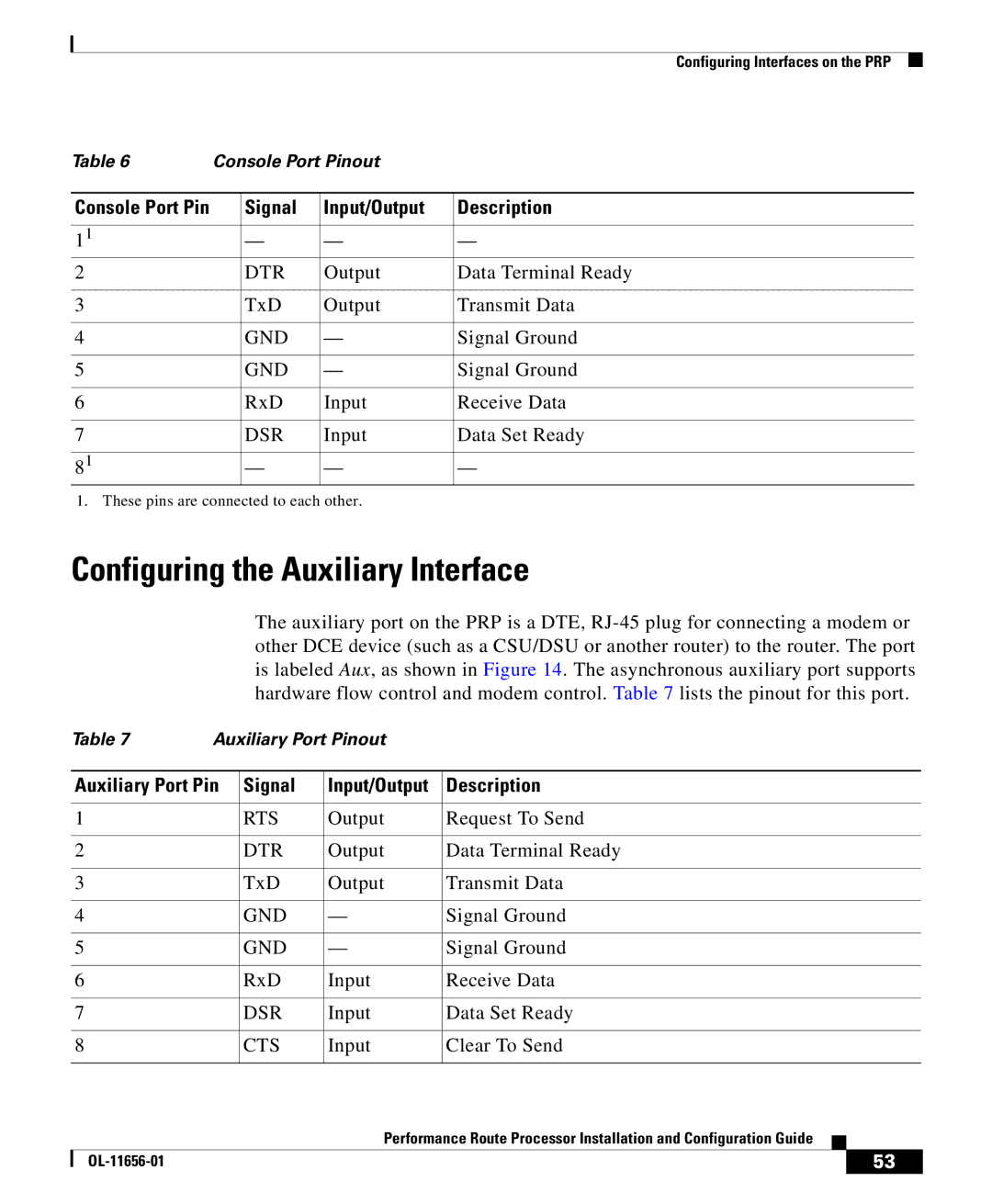
Table 6 | Console Port Pinout |
| ||
|
|
|
|
|
Console Port Pin |
| Signal | Input/Output | Description |
|
|
|
|
|
11 |
| — | — | — |
2 |
| DTR | Output | Data Terminal Ready |
|
|
|
|
|
3 |
| TxD | Output | Transmit Data |
|
|
|
|
|
4 |
| GND | — | Signal Ground |
|
|
|
|
|
5 |
| GND | — | Signal Ground |
|
|
|
|
|
6 |
| RxD | Input | Receive Data |
|
|
|
|
|
7 |
| DSR | Input | Data Set Ready |
|
|
|
|
|
81 |
| — | — | — |
1. These pins are connected to each other.
Configuring the Auxiliary Interface
The auxiliary port on the PRP is a DTE,
Table 7 | Auxiliary Port Pinout |
|
|
| |||
|
|
|
| ||||
| Auxiliary Port Pin | Signal | Input/Output | Description | |||
|
|
|
|
| |||
1 |
| RTS | Output | Request To Send | |||
|
|
|
|
| |||
2 |
| DTR | Output | Data Terminal Ready | |||
|
|
|
|
| |||
3 |
| TxD | Output | Transmit Data | |||
|
|
|
|
| |||
4 |
| GND | — | Signal Ground | |||
|
|
|
|
| |||
5 |
| GND | — | Signal Ground | |||
|
|
|
|
| |||
6 |
| RxD | Input | Receive Data | |||
|
|
|
|
| |||
7 |
| DSR | Input | Data Set Ready | |||
|
|
|
|
| |||
8 |
| CTS | Input | Clear To Send | |||
|
|
|
|
|
|
|
|
|
|
|
| Performance Route Processor Installation and Configuration Guide |
|
| |
|
|
|
|
| |||
|
|
|
|
|
| 53 | |
|
|
|
|
|
| ||