Chapter 4 Troubleshooting the Installation
Troubleshooting an AC Power Subsystem
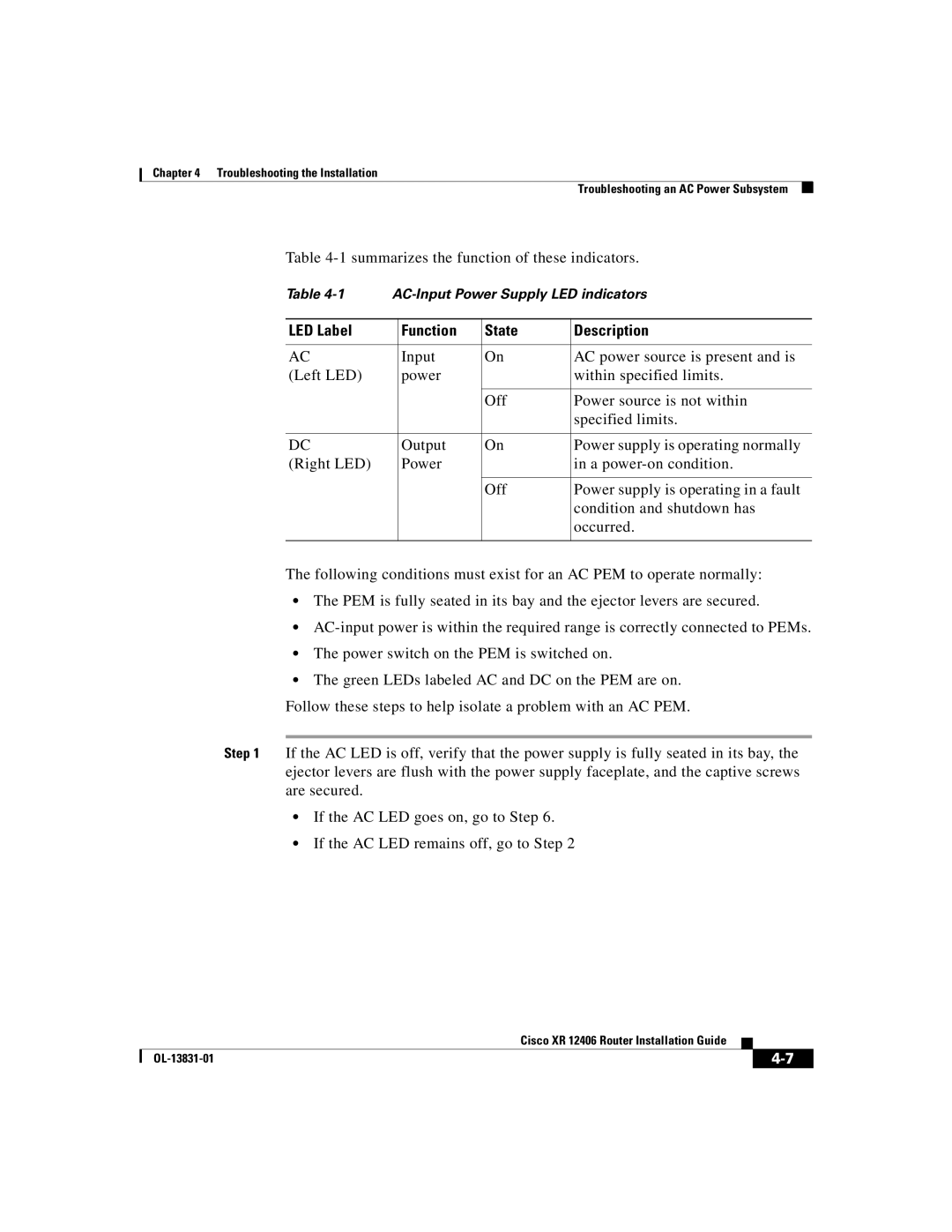
Table 4-1 summarizes the function of these indicators.
Table | ||||
|
|
|
|
|
LED Label |
| Function | State | Description |
|
|
|
|
|
AC |
| Input | On | AC power source is present and is |
(Left LED) |
| power |
| within specified limits. |
|
|
|
|
|
|
|
| Off | Power source is not within |
|
|
|
| specified limits. |
|
|
|
|
|
DC |
| Output | On | Power supply is operating normally |
(Right LED) |
| Power |
| in a |
|
|
|
|
|
|
|
| Off | Power supply is operating in a fault |
|
|
|
| condition and shutdown has |
|
|
|
| occurred. |
|
|
|
|
|
The following conditions must exist for an AC PEM to operate normally:
•The PEM is fully seated in its bay and the ejector levers are secured.
•
•The power switch on the PEM is switched on.
•The green LEDs labeled AC and DC on the PEM are on.
Follow these steps to help isolate a problem with an AC PEM.
Step 1 If the AC LED is off, verify that the power supply is fully seated in its bay, the ejector levers are flush with the power supply faceplate, and the captive screws are secured.
•If the AC LED goes on, go to Step 6.
•If the AC LED remains off, go to Step 2
|
| Cisco XR 12406 Router Installation Guide |
|
|
|
|
| ||
|
|
|
| |
|
|
|
