Chapter 3 Installing the Cisco XR 12406 Router
Powering On the
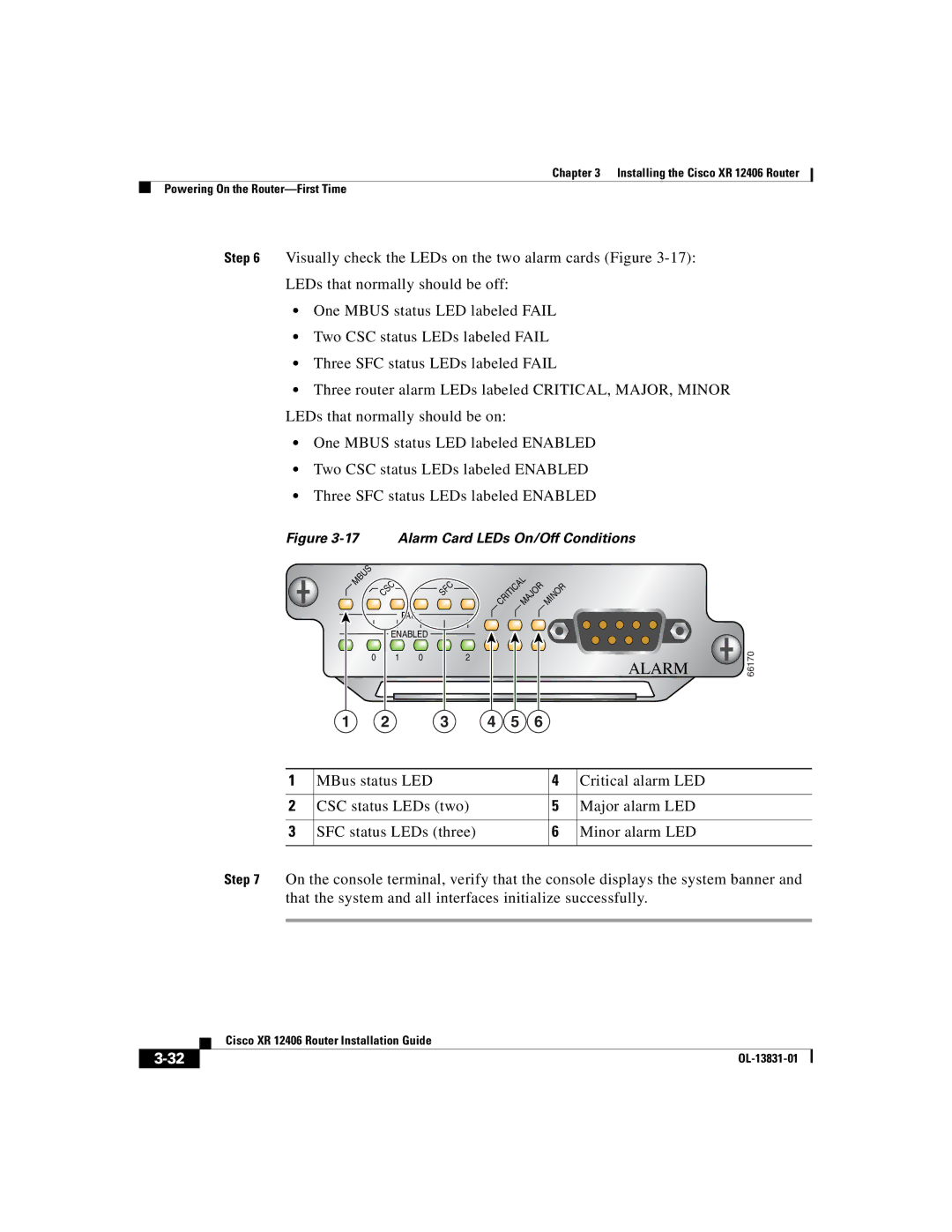
Step 6 Visually check the LEDs on the two alarm cards (Figure
LEDs that normally should be off:
•One MBUS status LED labeled FAIL
•Two CSC status LEDs labeled FAIL
•Three SFC status LEDs labeled FAIL
•Three router alarm LEDs labeled CRITICAL, MAJOR, MINOR LEDs that normally should be on:
•One MBUS status LED labeled ENABLED
•Two CSC status LEDs labeled ENABLED
•Three SFC status LEDs labeled ENABLED
Figure 3-17 Alarm Card LEDs On/Off Conditions
MBUS | CSC |
| SFC |
| CRITICALMAJOR | MINOR |
| |
|
|
|
| |||||
|
|
|
|
|
|
| ||
|
| FAIL |
|
|
|
|
|
|
| ENABLED |
|
|
|
|
| 66170 | |
0 | 1 | 0 | 1 | 2 |
|
| ALARM | |
1 | 2 |
| 3 | 4 | 5 | 6 |
|
|
1 | MBus status LED | 4 | Critical alarm LED |
|
|
|
|
2 | CSC status LEDs (two) | 5 | Major alarm LED |
|
|
|
|
3 | SFC status LEDs (three) | 6 | Minor alarm LED |
|
|
|
|
Step 7 On the console terminal, verify that the console displays the system banner and that the system and all interfaces initialize successfully.
Cisco XR 12406 Router Installation Guide
| ||
|