Cisco XR 12406 Router Installation Guide
Page
Cisco XR 12406 Router Installation Guide
Page
Purpose
Features
Alarm Cards
Line Cards
Laser Safety
Installing a Router
Connecting to the Console and Auxiliary Ports
Removing and Replacing a Switch Fabric Card
Powering Off the Router
Safety Recommendations
Translated Safety Warnings and Agency Approvals A-9
Contents Cisco XR 12406 Router Installation Guide
Audience
Purpose
Installation Guide Organization
Document Conventions
Xiii
Xiv
Cisco XR 12406 Router Overview
Router Description
Cisco XR 12406 Router-Front View
Cisco XR 12406 Router-Rear View
Features
Cisco XR 12406 Router Overview Features
Physical and Functional Description
Route Processor
OL-13831-01
Line Cards
Sample Line Cards
Multigigabit Crossbar Switch Fabric
Switch Fabric Card Types
Switch Fabric Switching Capacity and Router Type
Alarm Cards
Switch Fabric Redundancy
Alarm Output Function
Alarm
Alarm Card Status
Clock and Scheduler Card and Switch Fabric Card Status
Power Source Monitoring
Power Subsystems
Alarm Relay Contact Connector
AC Power Subsystem
AC PDU
AC Power Distribution Unit
AC-Input Power Supply
AC-Input Power Supply
LED Label Function State Description
DC Power Subsystem
DC PDU
DC Power Distribution Unit
DC-Input Power Entry Module
DC-Input Power Entry Module
LED Label Color Function
Green PEM is operating normally in a powered-on Condition
Miswire
Output OK
Power Distribution
Blower Module
Top view
Chassis Backplane and Maintenance Bus
Device Discovery
Power-on and Power-off Control
Diagnostics
Code Download
Environmental Monitoring and Alarms
Air Filters
11 Air Filter Locations
Cable-Management System
12 Chassis Cable-Management System
Field-Replaceable Units
Technical Specifications
OL-13831-01
Preparing for Installation
Safety and Compliance
Tools and Equipment
General Safety Guidelines
Compliance and Safety Information
Preventing Electrostatic Discharge Damage
Attaching an ESD-Preventive Strap
57082
Laser Safety
Lifting Guidelines
Safety with Electricity
Rack-Mounting Guidelines
Installation Site Requirements
Types of Equipment Racks
Equipment Dimensions and Site Layout
17.234 23.137 30.877 740 18.950
Preparing for Installation Installation Site Requirements
Ventilation
Environmental Guidelines
Airflow
Power Connection Guidelines
Temperature and Humidity
Power Connection Guidelines for AC-Powered Routers
Label Description Cisco Product Number
Power Connection Guidelines for DC-Powered Routers
AC Power Plugs
Grounding Connections
Supplemental Bonding and Grounding Port for Nebs Compliance
Place ground wire in the lug Crimp the lug
Crimping the Lug
Site Wiring
Electromagnetic Interference
Unpacking and Repacking the Router
Distance Limitations
Site Preparation Checklist
Transporting a Cisco XR 12000 Series Router
Date
Initials
OL-13831-01
Installing the Cisco XR 12406 Router
Installing a Router
Required Tools
Rails
Installing the Rack-Mounting Brackets-Optional
Follow a through c to mount the left rack-mount bracket
Use a screwdriver to tighten all the screws
Installing the Optional Rack-Mount Brackets
Installing Center-Mounting Brackets optional
Lower and Upper Center-Mounting Brackets
Installing the Chassis in a Rack
Chassis Mounting Bracket Holes
Installing the Chassis on a Tabletop or Flat Surface
Supplemental Bonding and Grounding Connections
Supplemental Bonding and Grounding Port for Nebs Compliance
Cable Lug
Place ground wire in the lug Crimp the lug
Connecting RP and Line Card Cables
Chassis Cable-Management Bracket
Connecting Alarm Card Cables
Connecting to the Console and Auxiliary Ports
PRP Console and Auxiliary Port Connections
PRP Auxiliary Port Signals
PRP Console Port Signals
Console Port Pin Signal Input/Output Description
RTS
Installing a Flash Memory Card
Signal Input/Output Description
CTS
Connecting the PRP to an Ethernet Network
Flash Memory Card Slot Opening
Cisco XR 12406 Router Installation Guide
PRP Ethernet Connections
RJ-45 receptacle Category 5 UTP cable with plug
Ethernet Port Pin Signal Description
Parameter RJ-45
Lists Ieee 802.3u physical characteristics for 100BASE-TX
Connecting to an AC Power Source
Parameter
Router Power Combination
AC PDU
14 AC Power Distribution Unit
Connecting to a DC Power Source
Captive screws four
Locate the DC power blocks on the back of the PDU Figure
DC PDU
Power a
Powering On the Router-First Time
OL-13831-01
Alarm
Boot Process Overview
Manually Booting the System
External Network Interface
Starting the Router and Observing Initial Conditions
OL-13831-01
RP Alphanumeric LED
Display Meaning Source
PRI
RP Interfaces Using the RP LEDs
RP IOS
SEC
Indicates link activity
Indicates the port is enabled
Link
Indicates data transmission
Manually Booting the System
OL-13831-01
Troubleshooting the Installation
Identifying Startup Problems
Cisco XR 12406 Router Installation Guide
Using the System LEDs to Troubleshoot
Problem-Solving with Subsystems
OL-13831-01
Troubleshooting an AC Power Subsystem
AC-Input Power Supply LEDs
Summarizes the function of these indicators
Cisco XR 12406 Router Installation Guide
Troubleshooting a DC Power Subsystem
Shows the location of the LEDs on the DC PEM
Amber Indicates input is wired backward at PDU input
DC-Input Power Entry Module LEDs
OL-13831-01
Cisco XR 12406 Router Installation Guide
Troubleshooting the Processor Subsystem
Troubleshooting the RP
Low memory on the RP is being tested RP ROM monitor
Display Definition Source
Test MEM
RP LEDs
Cisco XR 12406 Router Installation Guide
LED Display Indications
IOS
Troubleshooting the Line Cards
RP is enabled and recognized by the system
Cisco XR IOS software is up and running
Display1 Definition Source
LED Display1 Indications2
Troubleshooting the Alarm Cards
Shows the location of the alarm card LEDs
Monitoring Switch Fabric Card Status
Monitoring Alarm Card Status
Monitoring Clock Scheduler Card Status
Monitoring Critical, Major, and Minor Alarm Status
Troubleshooting the Cooling Subsystem
Shows the location of the LEDs on the blower module
Blower Module Location and Features
OL-13831-01
Cisco XR 12406 Router Installation Guide
Maintaining the Router
Maintaining the Router
Powering Off the Router
Installing the Front Cover
Removing and Installing the Front Cover
Removing the Front Cover
Removing or Installing the Front Cover
Release buttons
Removing and Replacing the Air Filters
Air filter door Air filters
Removing the Air Filters
Removing and Replacing the Blower Module
Cisco XR 12404 Router Air Filter Direction of Air Flow
Carrying handle Captive screws 2 on each side
Removing the Blower Module
Cisco XR 12406 Router Installation Guide
Carrying handle Guide pins Captive screws 2 on each side
Installing the Blower Module
Troubleshooting the Blower Installation
Removing and Replacing an AC Power Entry Module
Installation Guidelines
Power off the faulty PEM see item 3 in Figure
AC PEM
Releasing the AC Power Supply
Seating the AC Power Supply
Troubleshooting the AC Power Entry Module Installation
Cisco XR 12406 Router Installation Guide
Removing and Replacing an AC PDU
Unseating the AC Power Supply
10 AC Power Distribution Unit
11 Removing the Blower Module
12 Removing the AC PDU
13 Installing the Blower Module
14 Seating the AC Power Supply
Removing and Replacing a DC PEM
Power off the faulty PEM item 3 in Figure
DC PEM
16 Releasing the DC Power Supply
17 Seating the DC Power Supply
Troubleshooting the DC Power Supply Installation
Removing and Replacing a DC PDU
18 DC Power Entry Module Components
19 Unseating the DC Power Supply
20 Removing the Blower Module
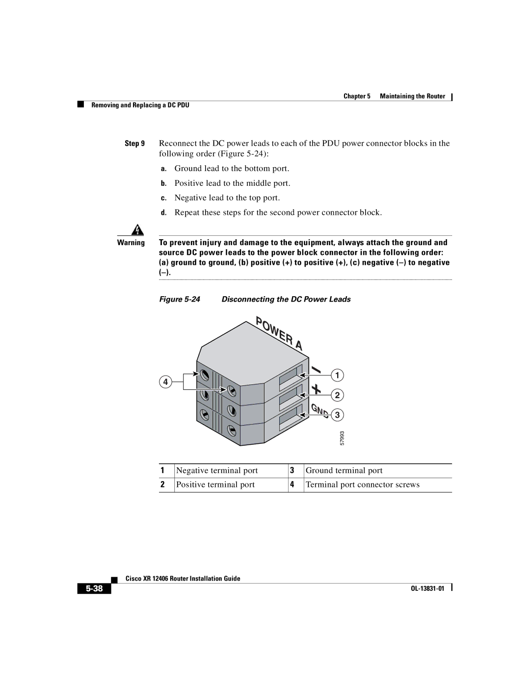
21 Disconnecting the DC Power Leads
Negative -, b positive +, c ground
22 Removing the DC PDU
23 Installing the Blower Module
24 Disconnecting the DC Power Leads
25 Seating a DC Power Supply
Troubleshooting the DC PDU Installation
26 DC Power Entry Module Components
Removing and Replacing an RP or a Line Card
27 Cisco XR 12406 Router Card Cage Slot Locations
OL-13831-01
28 Removing an RP or Line Card from the Card Cage
OL-13831-01
Attaching the Cable-Management Bracket and Connecting Cables
Repeat steps 1 through 3 for any remaining line cards
29 Line Card Cable-Management Bracket
30 Line Card Cable-Management Brackets with Velcro Straps
OL-13831-01
31 CSC, SFC, and Alarm Card Slot Locations
Removing and Replacing a Clock Scheduler Card
CSC
Verifying the Installation of the Clock Scheduler Card
Ejector lever
Removing and Replacing a Switch Fabric Card
SFC
Captive screw
Verifying the Installation of the Switch Fabric Card
Removing and Replacing an Alarm Card
Alarm card Captive screw
Verifying the Installation of the Alarm Card
35 shows the location of the alarm card LEDs
Upgrading the RP and Line Card Memory
Specifications
Description Value
Table A-2 AC-Input Power Supply Electrical Specifications
Table A-3 DC Power Entry Module Electrical Specifications
Table A-4 Cisco XR 12406 Router Environmental Specifications
Alarm Card Alarm Relay Connector Specifications
Pin Name Definition
USA
Compliance Information
Country Standard Requirements Class Up to 1 GHz
Etsi
Test Type or Specification Applies to Class/Level/Criteria
Category Approval Agency and Requirement
Etsi Specifications
Nebs Requirements
ACA TS001
Electromagnetic Compatibility Regulatory Statements
Translated Safety Warnings and Agency Approvals
FCC Class a Compliance
Canada
Europe EU
Vcci Class a Notice for Japan
Class a Notice for Hungary
Regulatory, Compliance, and Safety Information
Compliance Label
Compliance information label
Router Performance Upgrades and Model Identification
Switch Fabric Identification
Repacking the Router
Transporting and Storing the Router
Shipping Package Overview
Figure B-1 Cisco XR 12406 Router Packing Components
Safety Recommendations
Repacking the Router
Figure B-2 Securing the Router to the Pallet Base
Appendix B Repacking the Router
Figure B-3 Packaged Router Secured to Pallet
OL-13831-01
Critical, major, and minor LEDs 4-24removing and installing
Numerics
CSC
IN-2
EMC
EMI
Nebs
Field diagnostics 4-18field replaceable unit
GRP
Compliance 1-5,A-8
PRP
IN-5
IN-6
IN-7
IN-8


 +
+ 

 GND
GND