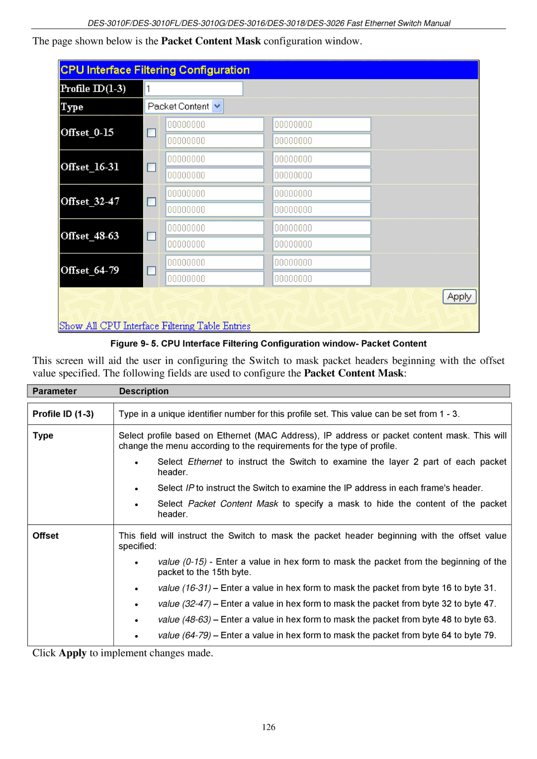
The page shown below is the Packet Content Mask configuration window.
Figure 9- 5. CPU Interface Filtering Configuration window- Packet Content
This screen will aid the user in configuring the Switch to mask packet headers beginning with the offset value specified. The following fields are used to configure the Packet Content Mask:
Parameter Description
Profile ID (1-3)
Type
Offset
Type in a unique identifier number for this profile set. This value can be set from 1 - 3.
Select profile based on Ethernet (MAC Address), IP address or packet content mask. This will change the menu according to the requirements for the type of profile.
•Select Ethernet to instruct the Switch to examine the layer 2 part of each packet header.
•Select IP to instruct the Switch to examine the IP address in each frame's header.
•Select Packet Content Mask to specify a mask to hide the content of the packet header.
This field will instruct the Switch to mask the packet header beginning with the offset value specified:
•value
•value
•value
•value
•value
Click Apply to implement changes made.
126