Ethernet type
header.
Selecting this option instructs the Switch to examine the Ethernet type value in each frame's header.
Click Apply to set this entry in the Switch’s memory.
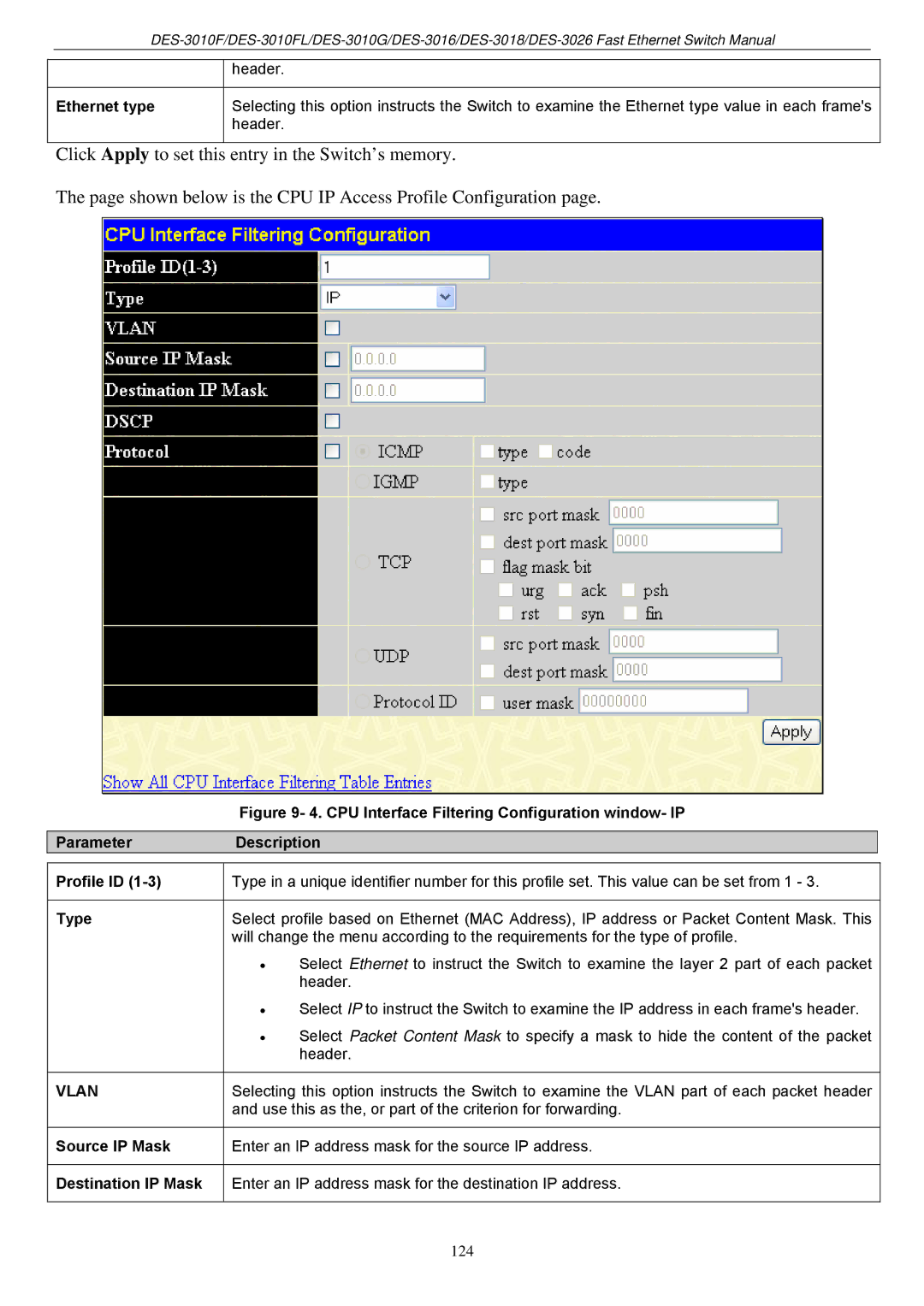
The page shown below is the CPU IP Access Profile Configuration page.
Figure 9- 4. CPU Interface Filtering Configuration window- IP
ParameterDescription
Profile ID (1-3)
Type
VLAN
Source IP Mask
Destination IP Mask
Type in a unique identifier number for this profile set. This value can be set from 1 - 3.
Select profile based on Ethernet (MAC Address), IP address or Packet Content Mask. This will change the menu according to the requirements for the type of profile.
•Select Ethernet to instruct the Switch to examine the layer 2 part of each packet header.
•Select IP to instruct the Switch to examine the IP address in each frame's header.
•Select Packet Content Mask to specify a mask to hide the content of the packet header.
Selecting this option instructs the Switch to examine the VLAN part of each packet header and use this as the, or part of the criterion for forwarding.
Enter an IP address mask for the source IP address.
Enter an IP address mask for the destination IP address.
124