Straight
|
|
|
|
|
|
|
|
|
|
|
|
|
|
| Contact |
|
| MDI Signal |
|
| ||||||||||||||
|
|
|
|
|
|
|
|
|
|
|
|
|
|
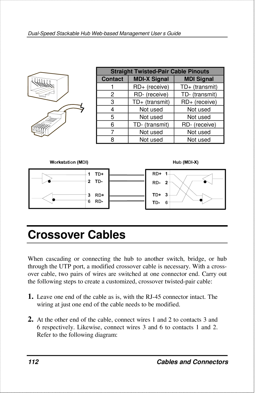
| 1 | RD+ (receive) |
| TD+ (transmit) |
|
| ||||||||||||||
|
|
|
|
|
|
|
|
|
|
|
|
|
|
| 2 | RD- (receive) |
| TD- (transmit) |
|
| ||||||||||||||
|
|
|
|
|
|
|
|
|
|
|
|
|
|
| 3 | TD+ (transmit) |
| RD+ (receive) |
|
| ||||||||||||||
|
|
|
|
|
|
|
|
|
|
|
|
|
|
| 4 | Not used |
|
| Not used |
|
| |||||||||||||
|
|
|
|
|
|
|
|
|
|
|
|
|
|
| 5 | Not used |
|
| Not used |
|
| |||||||||||||
|
|
|
|
|
|
|
|
|
|
|
|
|
|
| 6 | TD- (transmit) |
|
| RD- (receive) |
|
| |||||||||||||
|
|
|
|
|
|
|
|
|
|
|
|
|
|
| 7 | Not used |
|
| Not used |
|
| |||||||||||||
|
|
|
|
|
|
|
|
|
|
|
|
|
|
| 8 | Not used |
|
| Not used |
|
| |||||||||||||
|
|
|
|
|
|
|
|
|
|
|
|
|
|
|
|
|
|
|
|
|
|
|
|
|
|
|
|
|
|
|
|
|
|
|
|
|
|
|
|
|
|
|
|
|
|
|
|
|
|
|
|
|
|
|
|
|
|
|
|
|
|
|
|
|
|
|
|
|
|
|
|
|
|
|
|
|
|
|
|
|
|
|
|
|
|
|
|
|
|
|
|
|
|
|
|
|
|
|
|
|
|
|
|
|
|
|
|
|
|
|
|
|
|
|
|
|
|
|
|
|
|
|
|
|
|
|
|
|
|
|
|
|
|
|
|
|
|
|
|
|
|
|
|
|
|
|
|
|
|
|
|
|
|
|
|
|
|
|
|
|
|
|
|
|
|
|
|
|
|
|
|
|
|
|
|
|
|
|
|
|
|
|
|
|
|
|
|
|
|
|
|
|
|
|
|
|
|
|
|
|
|
|
|
|
|
|
|
|
|
|
|
|
|
|
|
|
|
|
|
|
|
|
|
|
|
|
|
|
|
|
|
|
|
|
|
|
|
|
|
|
|
|
|
|
|
|
|
|
|
|
|
|
|
|
|
|
|
|
|
|
|
|
|
|
|
|
|
|
|
|
|
|
|
|
|
|
|
|
|
Crossover Cables
When cascading or connecting the hub to another switch, bridge, or hub through the UTP port, a modified crossover cable is necessary. With a cross- over cable, two pairs of wires are switched at one connector end. Carry out the following steps to create a customized, crossover
1.Leave one end of the cable as is, with the
2.At the other end of the cable, connect wires 1 and 2 to contacts 3 and 6 respectively. Likewise, connect wires 3 and 6 to contacts 1 and 2. Refer to the following diagram:
112 | Cables and Connectors |