Removing the Front Bezel
Use the following procedure to remove the front bezel:
1.Remove the computer covers.
See the previous subsection, “Removing the Com- puter Covers.”
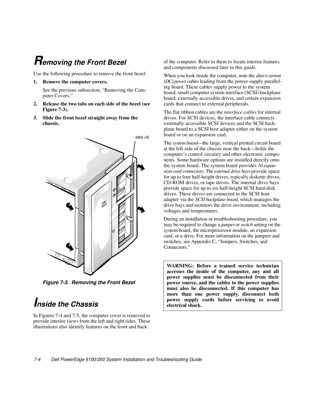
2.Release the two tabs on each side of the bezel (see Figure
3.Slide the front bezel straight away from the chassis.
tabs (4)
Figure 7-3. Removing the Front Bezel
Inside the Chassis
In Figures 7-4 and 7-5, the computer cover is removed to provide interior views from the left and right sides. These illustrations also identify features on the front and back
of the computer. Refer to them to locate interior features and components discussed later in this guide.
When you look inside the computer, note the direct current (DC) power cables leading from the
The flat ribbon cables are the interface cables for internal drives. For SCSI devices, the interface cable connects externally accessible SCSI devices and the SCSI back- plane board to a SCSI host adapter either on the system board or on an expansion card.
The system
During an installation or troubleshooting procedure, you may be required to change a jumper or switch setting on the system board, the microprocessor module, an expansion card, or a drive. For more information on the jumpers and switches, see Appendix C, “Jumpers, Switches, and Connectors.”
WARNING: Before a trained service technician accesses the inside of the computer, any and all power supplies must be disconnected from their power source, and the cables to the power supplies must also be disconnected. If this computer has more than one power supply, disconnect both power supply cords before servicing to avoid electrical shock.