8.Unpack the new microprocessor.
CAUTION: Be careful not to bend any of the pins when unpacking the microprocessor from its socket. Bending the pins can permanently damage the microprocessor.
If any of the pins on the microprocessor appear bent, see Chapter 11, “Getting Help,” for instructions on obtaining technical assistance from Dell.
9.Make sure the release lever on the processor socket you are installing to is up so that the socket is ready for the new microprocessor.
10.Align the
NOTE: Identifying the
Identify the
Figure 8-10. Pin-1 Identification
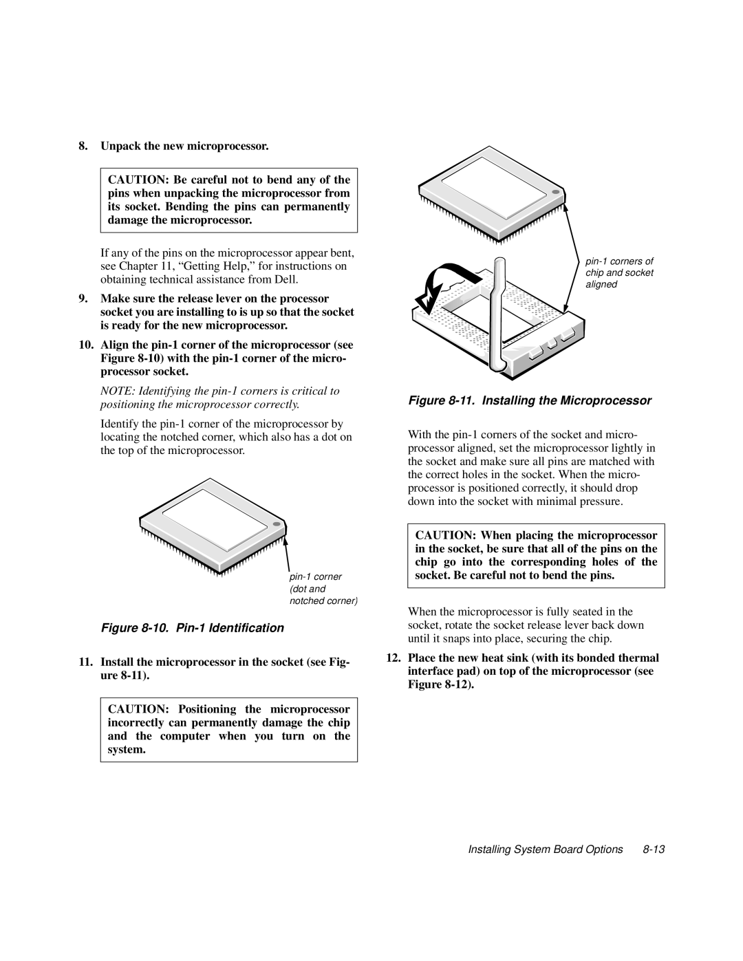
11.Install the microprocessor in the socket (see Fig- ure 8-11).
CAUTION: Positioning the microprocessor incorrectly can permanently damage the chip and the computer when you turn on the system.
Figure 8-11. Installing the Microprocessor
With the
CAUTION: When placing the microprocessor in the socket, be sure that all of the pins on the chip go into the corresponding holes of the socket. Be careful not to bend the pins.
When the microprocessor is fully seated in the socket, rotate the socket release lever back down until it snaps into place, securing the chip.
12.Place the new heat sink (with its bonded thermal interface pad) on top of the microprocessor (see Figure
Installing System Board Options |