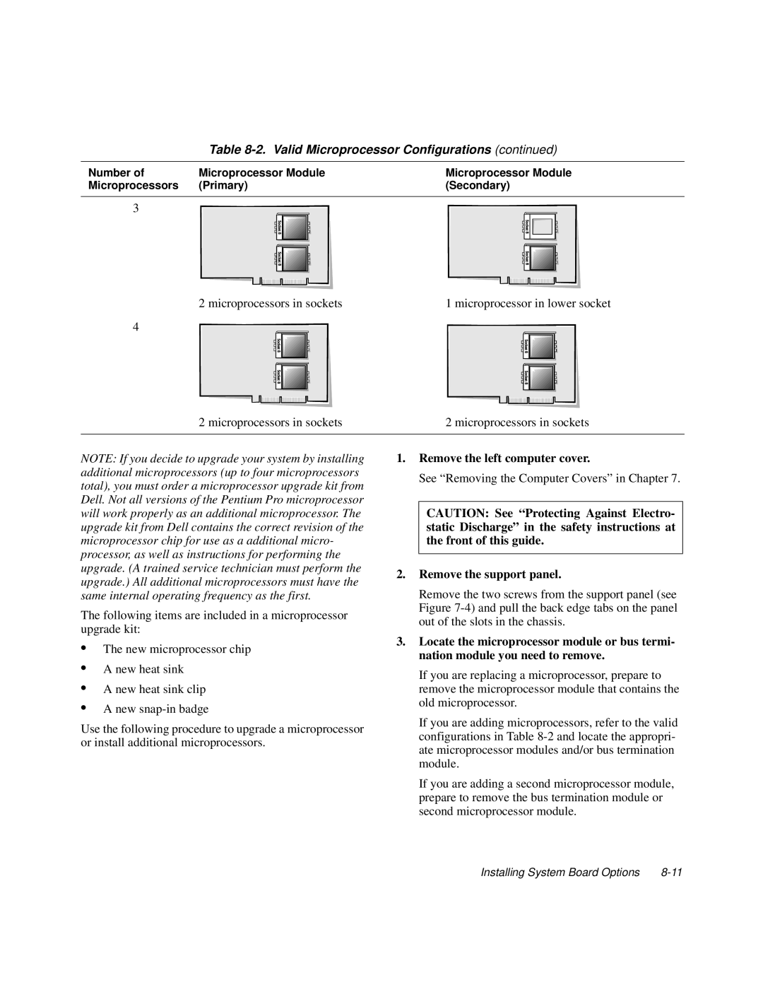
Table 8-2. Valid Microprocessor Configurations (continued)
Number of | Microprocessor Module | Microprocessor Module |
Microprocessors | (Primary) | (Secondary) |
|
|
|
3
2 microprocessors in sockets | 1 microprocessor in lower socket |
4
2 microprocessors in sockets | 2 microprocessors in sockets |
|
|
NOTE: If you decide to upgrade your system by installing additional microprocessors (up to four microprocessors total), you must order a microprocessor upgrade kit from Dell. Not all versions of the Pentium Pro microprocessor will work properly as an additional microprocessor. The upgrade kit from Dell contains the correct revision of the microprocessor chip for use as a additional micro- processor, as well as instructions for performing the upgrade. (A trained service technician must perform the upgrade.) All additional microprocessors must have the same internal operating frequency as the first.
The following items are included in a microprocessor upgrade kit:
1.Remove the left computer cover.
See “Removing the Computer Covers” in Chapter 7.
CAUTION: See “Protecting Against Electro- static Discharge” in the safety instructions at the front of this guide.
2.Remove the support panel.
Remove the two screws from the support panel (see Figure
•The new microprocessor chip
•A new heat sink
•A new heat sink clip
•A new
Use the following procedure to upgrade a microprocessor or install additional microprocessors.
3.Locate the microprocessor module or bus termi- nation module you need to remove.
If you are replacing a microprocessor, prepare to remove the microprocessor module that contains the old microprocessor.
If you are adding microprocessors, refer to the valid configurations in Table
If you are adding a second microprocessor module, prepare to remove the bus termination module or second microprocessor module.
Installing System Board Options |