Removing and Replacing Front-Panel Inserts
To remove the
![]()
![]()
![]() tabs
tabs
Figure 9-2. Removing a Front-Panel Insert
To replace a
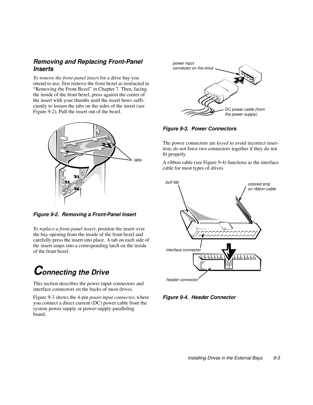
power input connector on the drive
![]() DC power cable (from the power supply)
DC power cable (from the power supply)
Figure 9-3. Power Connectors
The power connectors are keyed to avoid incorrect inser- tion; do not force two connectors together if they do not fit properly.
A ribbon cable (see Figure
pull tab | colored strip |
| |
| on ribbon cable |
interface connector
Connecting the Drive
This section describes the power input connectors and | header connector |
| |
interface connectors on the backs of most drives. |
|
Figure | Figure |
you connect a direct current (DC) power cable from the |
|
system power supply or |
|
board. |
|
Installing Drives in the External Bays |