•If two or more SCSI devices are installed, connect the devices as follows:
—Attach one of the devices to the end connector on the SCSI cable, and leave the terminator enabled on that device.
—The other end of the SCSI cable connects to the computer’s
—Disable the terminators on all other devices you attach to the cable.
The standard SCSI
See the documentation provided with the SCSI device for information on disabling the device’s terminator.
SCSI Cable
CAUTION: Dell recommends that you use only SCSI cables purchased from Dell. SCSI cables purchased elsewhere are not guaranteed to work reliably with the Dell PowerEdge 6100 systems.
The
•The connector at the end of the cable farthest away from the other five connectors attaches to the SCSI host adapter connector labeled “SCSI B” on the sys- tem board.
•The five connectors on the cable attach to devices in the external drive bays.
The
Installing a SCSI Device
To install an external SCSI device that uses the
1.Prepare the drive for installation.
Ground yourself by touching an unpainted metal sur- face on the back of the computer, unpack the drive, and compare the jumper and switch settings with
those in the drive documentation. (See “SCSI Con- figuration Information” earlier in this section for information on setting the drive’s SCSI ID number and enabling termination [if required].) Change any settings necessary for this system’s configuration.
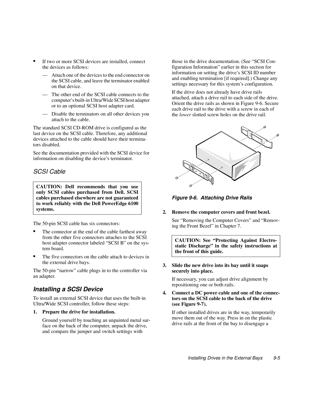
If the drive does not already have drive rails attached, attach a drive rail to each side of the drive. Orient the drive rails as shown in Figure
Figure 9-6. Attaching Drive Rails
2.Remove the computer covers and front bezel.
See “Removing the Computer Covers” and “Remov- ing the Front Bezel” in Chapter 7.
CAUTION: See “Protecting Against Electro- static Discharge” in the safety instructions at the front of this guide.
3.Slide the new drive into its bay until it snaps securely into place.
If necessary, you can adjust drive alignment by repositioning one or both rails.
4.Connect a DC power cable and one of the connec- tors on the SCSI cable to the back of the drive (see Figure
If other installed drives are in the way, temporarily move them out of the way. Press in on the plastic drive rails at the front of the bay to disengage a
Installing Drives in the External Bays |