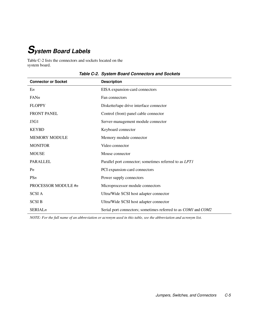
System Board Labels
Table
| Table |
|
|
Connector or Socket | Description |
|
|
En | EISA |
FANn | Fan connectors |
FLOPPY | Diskette/tape drive interface connector |
FRONT PANEL | Control (front) panel cable connector |
J3G1 | |
KEYBD | Keyboard connector |
MEMORY MODULE | Memory module connector |
MONITOR | Video connector |
MOUSE | Mouse connector |
PARALLEL | Parallel port connector; sometimes referred to as LPT1 |
Pn | PCI |
PSn | Power supply connectors |
PROCESSOR MODULE #n | Microprocessor module connectors |
SCSI A | Ultra/Wide SCSI host adapter connector |
SCSI B | Ultra/Wide SCSI host adapter connector |
SERIALn | Serial port connectors; sometimes referred to as COM1 and COM2 |
|
|
NOTE: For the full name of an abbreviation or acronym used in this table, see the abbreviation and acronym list.
Jumpers, Switches, and Connectors |
