When installing SIMMs, follow these guidelines:
•Install the SIMM with the pin 1 end aligned with the pin 1 end of the socket (see Figure
•Install a SIMM in socket J1 before socket J2, socket J2 before socket J3, and so on.
•All SIMMs in one bank must be the same size and speed, but SIMMs in bank 1 may differ in size from those in bank 2.
•SIMMs must be installed in groups of four, eight, or 16 only.
The following SIMM interleaving is supported:
•
•
•
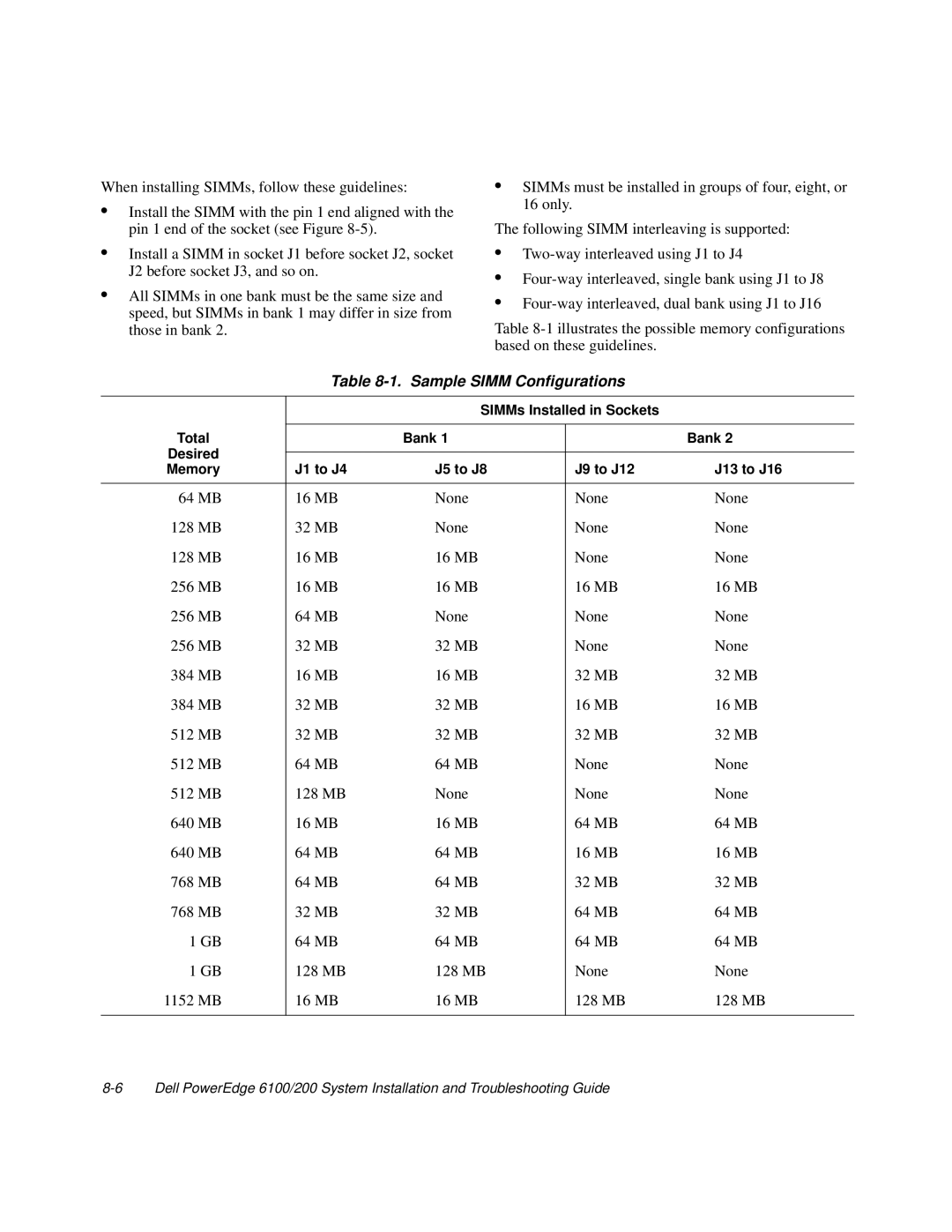
Table
Table 8-1. Sample SIMM Configurations
|
| SIMMs Installed in Sockets |
| |
Total |
|
|
|
|
| Bank 1 |
| Bank 2 | |
Desired |
|
|
|
|
|
|
|
| |
Memory | J1 to J4 | J5 to J8 | J9 to J12 | J13 to J16 |
|
|
|
|
|
64 MB | 16 MB | None | None | None |
128 MB | 32 MB | None | None | None |
128 MB | 16 MB | 16 MB | None | None |
256 MB | 16 MB | 16 MB | 16 MB | 16 MB |
256 MB | 64 MB | None | None | None |
256 MB | 32 MB | 32 MB | None | None |
384 MB | 16 MB | 16 MB | 32 MB | 32 MB |
384 MB | 32 MB | 32 MB | 16 MB | 16 MB |
512 MB | 32 MB | 32 MB | 32 MB | 32 MB |
512 MB | 64 MB | 64 MB | None | None |
512 MB | 128 MB | None | None | None |
640 MB | 16 MB | 16 MB | 64 MB | 64 MB |
640 MB | 64 MB | 64 MB | 16 MB | 16 MB |
768 MB | 64 MB | 64 MB | 32 MB | 32 MB |
768 MB | 32 MB | 32 MB | 64 MB | 64 MB |
1 GB | 64 MB | 64 MB | 64 MB | 64 MB |
1 GB | 128 MB | 128 MB | None | None |
1152 MB | 16 MB | 16 MB | 128 MB | 128 MB |
|
|
|
|
|