![]() clip
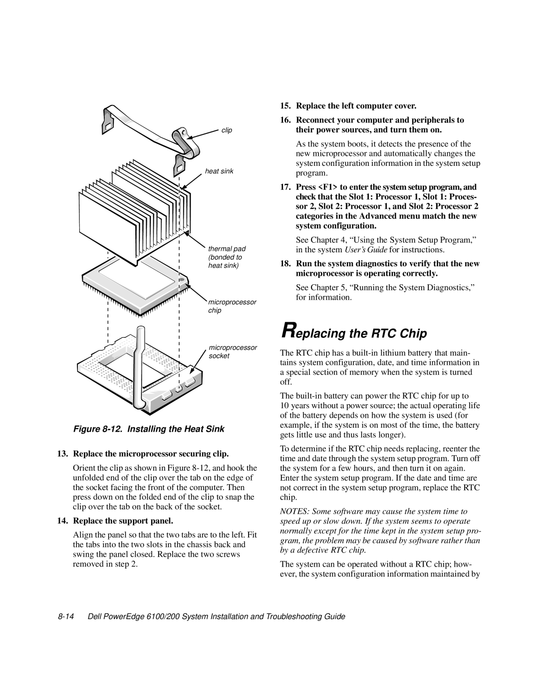
clip
heat sink
thermal pad (bonded to heat sink)
microprocessor chip
microprocessor socket
Figure 8-12. Installing the Heat Sink
13.Replace the microprocessor securing clip.
Orient the clip as shown in Figure
14.Replace the support panel.
Align the panel so that the two tabs are to the left. Fit the tabs into the two slots in the chassis back and swing the panel closed. Replace the two screws removed in step 2.
15.Replace the left computer cover.
16.Reconnect your computer and peripherals to their power sources, and turn them on.
As the system boots, it detects the presence of the new microprocessor and automatically changes the system configuration information in the system setup program.
17.Press <F1> to enter the system setup program, and check that the Slot 1: Processor 1, Slot 1: Proces- sor 2, Slot 2: Processor 1, and Slot 2: Processor 2 categories in the Advanced menu match the new system configuration.
See Chapter 4, “Using the System Setup Program,” in the system User’s Guide for instructions.
18.Run the system diagnostics to verify that the new microprocessor is operating correctly.
See Chapter 5, “Running the System Diagnostics,” for information.
Replacing the RTC Chip
The RTC chip has a
The
10 years without a power source; the actual operating life of the battery depends on how the system is used (for example, if the system is on most of the time, the battery gets little use and thus lasts longer).
To determine if the RTC chip needs replacing, reenter the time and date through the system setup program. Turn off the system for a few hours, and then turn it on again.
Enter the system setup program. If the date and time are not correct in the system setup program, replace the RTC chip.
NOTES: Some software may cause the system time to speed up or slow down. If the system seems to operate normally except for the time kept in the system setup pro- gram, the problem may be caused by software rather than by a defective RTC chip.
The system can be operated without a RTC chip; how- ever, the system configuration information maintained by
