Hardware Information
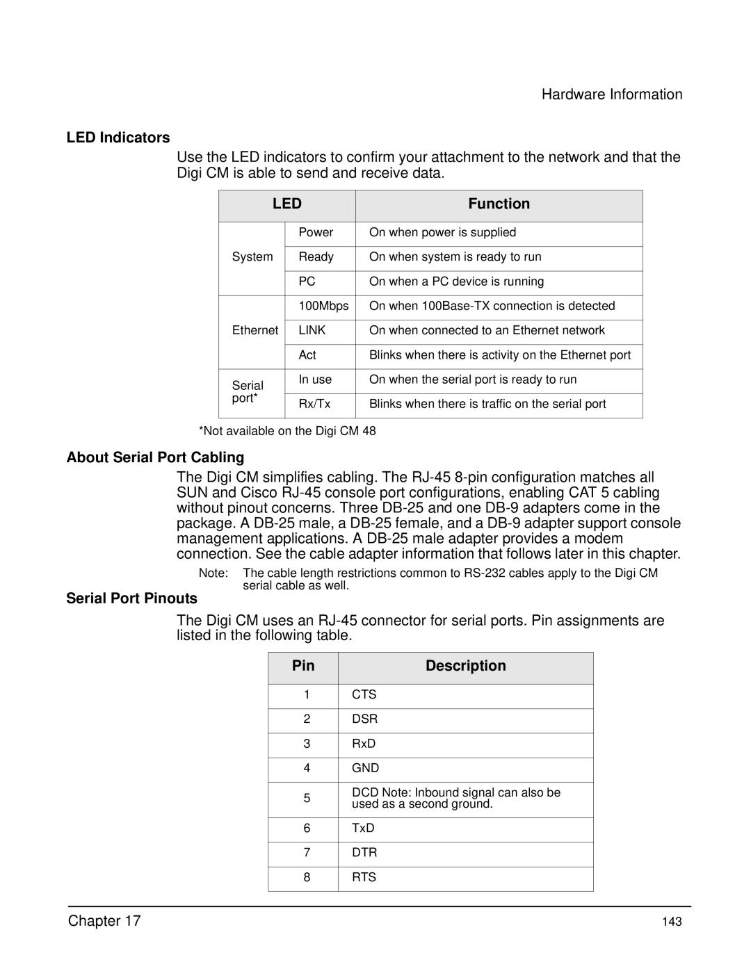
LED Indicators
Use the LED indicators to confirm your attachment to the network and that the Digi CM is able to send and receive data.
LED | Function | ||
|
|
| |
| Power | On when power is supplied | |
|
|
| |
System | Ready | On when system is ready to run | |
|
|
| |
| PC | On when a PC device is running | |
|
|
| |
| 100Mbps | On when | |
|
|
| |
Ethernet | LINK | On when connected to an Ethernet network | |
|
|
| |
| Act | Blinks when there is activity on the Ethernet port | |
|
|
| |
Serial | In use | On when the serial port is ready to run | |
|
| ||
port* |
|
| |
Rx/Tx | Blinks when there is traffic on the serial port | ||
| |||
|
|
| |
*Not available on the Digi CM 48
About Serial Port Cabling
The Digi CM simplifies cabling. The
Note: The cable length restrictions common to
Serial Port Pinouts
The Digi CM uses an
| Pin | Description |
|
|
|
|
|
| 1 | CTS |
|
|
|
|
|
| 2 | DSR |
|
|
|
|
|
| 3 | RxD |
|
|
|
|
|
| 4 | GND |
|
|
|
|
|
| 5 | DCD Note: Inbound signal can also be |
|
| used as a second ground. |
| |
|
|
| |
|
|
|
|
| 6 | TxD |
|
|
|
|
|
| 7 | DTR |
|
|
|
|
|
| 8 | RTS |
|
|
|
|
|
|
|
|
|
Chapter 17 | 143 |