01201138 | 0107 | 30 |
|
|
|
Notice | Date | Page |
|
|
|
9
9. Installation
INSTRUCTION
HANDBOOK
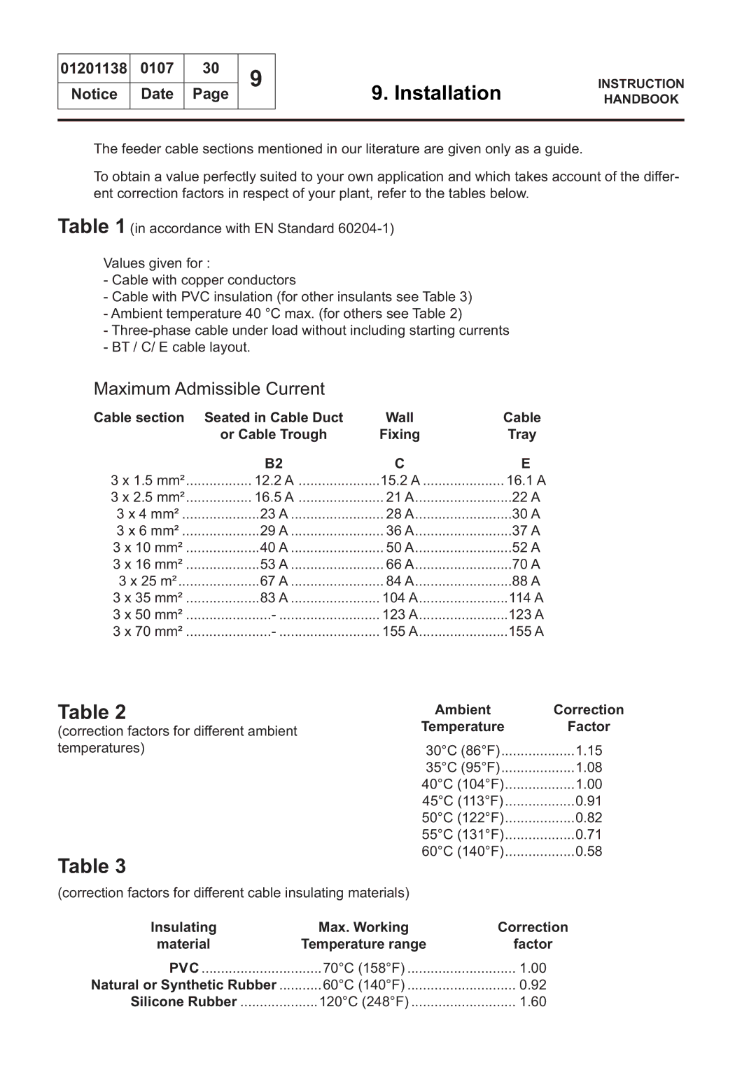
The feeder cable sections mentioned in our literature are given only as a guide.
To obtain a value perfectly suited to your own application and which takes account of the differ- ent correction factors in respect of your plant, refer to the tables below.
Table 1 (in accordance with EN Standard
Values given for :
-Cable with copper conductors
-Cable with PVC insulation (for other insulants see Table 3)
-Ambient temperature 40 °C max. (for others see Table 2)
-
-BT / C/ E cable layout.
Maximum Admissible Current
Cable section | Seated in Cable Duct | Wall | Cable |
| or Cable Trough | Fixing | Tray |
| B2 | C | E |
3 x 1.5 mm² | ................. 12.2 A | 15.2 A | ..................... 16.1 A |
3 x 2.5 mm² | ................. 16.5 A | 21 A | 22 A |
3 x 4 mm² | 23 A | 28 A | 30 A |
3 x 6 mm² | 29 A | 36 A | 37 A |
3 x 10 mm² | 40 A | 50 A | 52 A |
3 x 16 mm² | ...................53 A | 66 A | 70 A |
3 x 25 m² | 67 A | 84 A | 88 A |
3 x 35 mm² | ...................83 A | 104 A | 114 A |
3 x 50 mm² | 123 A | 123 A | |
3 x 70 mm² | 155 A | 155 A |
Table 2
(correction factors for different ambient temperatures)
Table 3
(correction factors for different cable insulating materials)
Ambient | Correction |
Temperature | Factor |
30°C (86°F) | 1.15 |
35°C (95°F) | 1.08 |
40°C (104°F) | 1.00 |
45°C (113°F) | 0.91 |
50°C (122°F) | 0.82 |
55°C (131°F) | 0.71 |
60°C (140°F) | 0.58 |
Insulating | Max. Working | Correction |
material | Temperature range | factor |
PVC | 70°C (158°F) | 1.00 |
Natural or Synthetic Rubber | 60°C (140°F) | 0.92 |
Silicone Rubber | 120°C (248°F) | 1.60 |
