01201138 | 0107 | 69 | 11 | 11. Machine | INSTRUCTION | |
Notice | Date | Page | operation | |||
HANDBOOK | ||||||
|
|
|
|
|
|
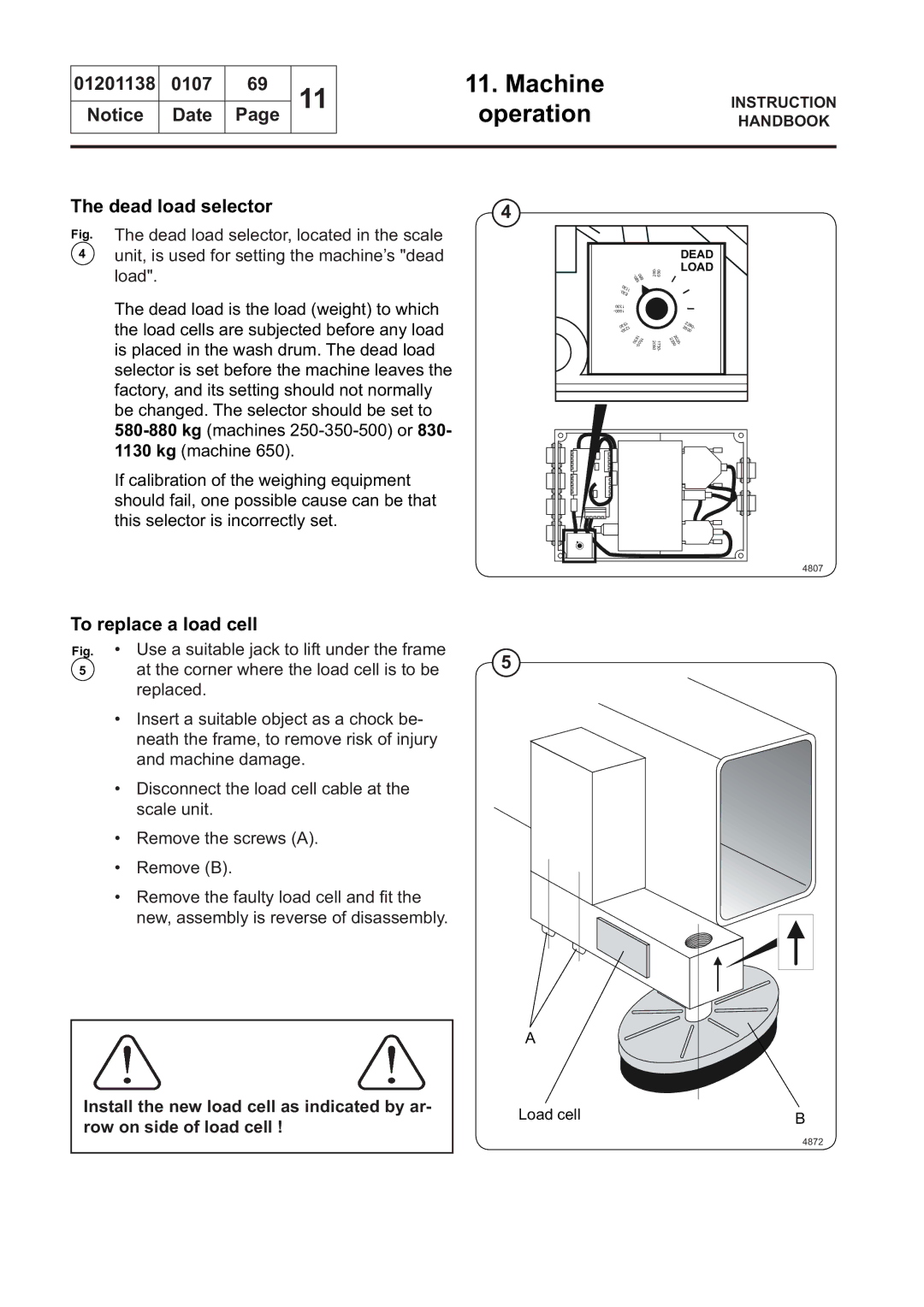
The dead load selector | 4 |
Fig. The dead load selector, located in the scale
4unit, is used for setting the machine’s "dead load".
The dead load is the load (weight) to which the load cells are subjected before any load is placed in the wash drum. The dead load selector is set before the machine leaves the factory, and its setting should not normally be changed. The selector should be set to
If calibration of the weighing equipment should fail, one possible cause can be that this selector is incorrectly set.
5
|
|
|
|
|
|
| 03 |
|
|
|
|
|
|
|
| ||||
|
|
|
|
|
|
| 11 |
|
|
|
|
|
|
|
| ||||
|
|
|
|
|
|
|
|
| 38 |
|
|
|
|
|
|
|
| ||
|
|
|
|
|
|
| 1330 |
|
|
|
|
|
|
|
|
|
| ||
|
|
|
|
|
|
|
|
|
|
|
|
|
|
|
|
| |||
|
|
|
|
|
|
|
|
|
| 1 |
|
|
|
|
|
|
|
| |
|
|
|
|
|
|
|
|
| 5 |
|
|
|
|
|
|
|
|
| |
|
|
|
|
|
|
| 3 |
| 1 |
|
|
|
|
|
|
|
| ||
|
|
|
|
|
|
| 0 |
|
|
|
|
|
|
|
|
|
| ||
|
|
|
|
|
|
|
|
|
| 2 |
|
|
|
|
|
|
|
| |
|
|
|
|
|
|
|
|
| 3 |
|
|
|
|
|
|
|
|
| |
|
|
|
|
|
|
| 0 |
|
|
|
|
|
|
|
|
|
| ||
|
|
|
|
|
|
| - |
|
|
|
|
|
| 1 |
|
|
|
| |
|
|
|
|
|
|
|
|
|
|
|
| 3 | 8 |
|
|
| 5 | 1 | |
|
|
|
|
|
|
|
|
|
|
| 0 |
|
|
| 0 | ||||
|
|
|
|
|
|
|
|
|
|
|
|
|
| 0 |
| ||||
|
|
|
|
|
|
|
|
|
|
|
|
|
| - |
|
|
|
| |
|
|
|
|
|
|
|
|
|
|
|
|
|
|
|
|
|
|
|
|
|
|
|
|
|
|
|
|
|
|
|
|
|
|
|
|
|
|
|
|
|
|
|
|
|
|
|
|
|
|
|
|
|
|
|
|
|
|
|
|
|
|
|
|
|
|
|
|
|
|
|
|
|
|
|
|
|
|
|
|
|
|
|
|
|
|
|
|
|
|
|
|
|
|
|
|
|
|
|
|
|
|
|
|
|
|
|
|
|
|
|
|
|
|
|
|
|
|
|
|
|
|
|
|
|
|
|
|
|
|
|
|
|
|
|
|
|
|
|
|
|
|
|
|
|
|
|
|
|
|
|
|
|
|
|
|
|
|
|
|
|
|
|
|
|
|
|
|
|
|
|
|
|
|
|
|
|
|
|
|
280- 650
1730- 2050
DEAD
LOAD
22 |
| |
26 | 80 | |
| - | |
00 |
| |
2 20 32 50 0-
4807
To replace a load cell
Fig.
5
• Use a suitable jack to lift under the frame
at the corner where the load cell is to be 5 replaced.
•Insert a suitable object as a chock be- neath the frame, to remove risk of injury and machine damage.
•Disconnect the load cell cable at the scale unit.
•Remove the screws (A).
•Remove (B).
•Remove the faulty load cell and fi t the new, assembly is reverse of disassembly.
Install the new load cell as indicated by ar- row on side of load cell !
A
Load cell | B |
| 4872 |
