INSTRUCTION
HANDBOOK
9. Installation
01201138 | 0107 | 31 |
|
|
|
Notice | Date | Page |
|
|
|
9
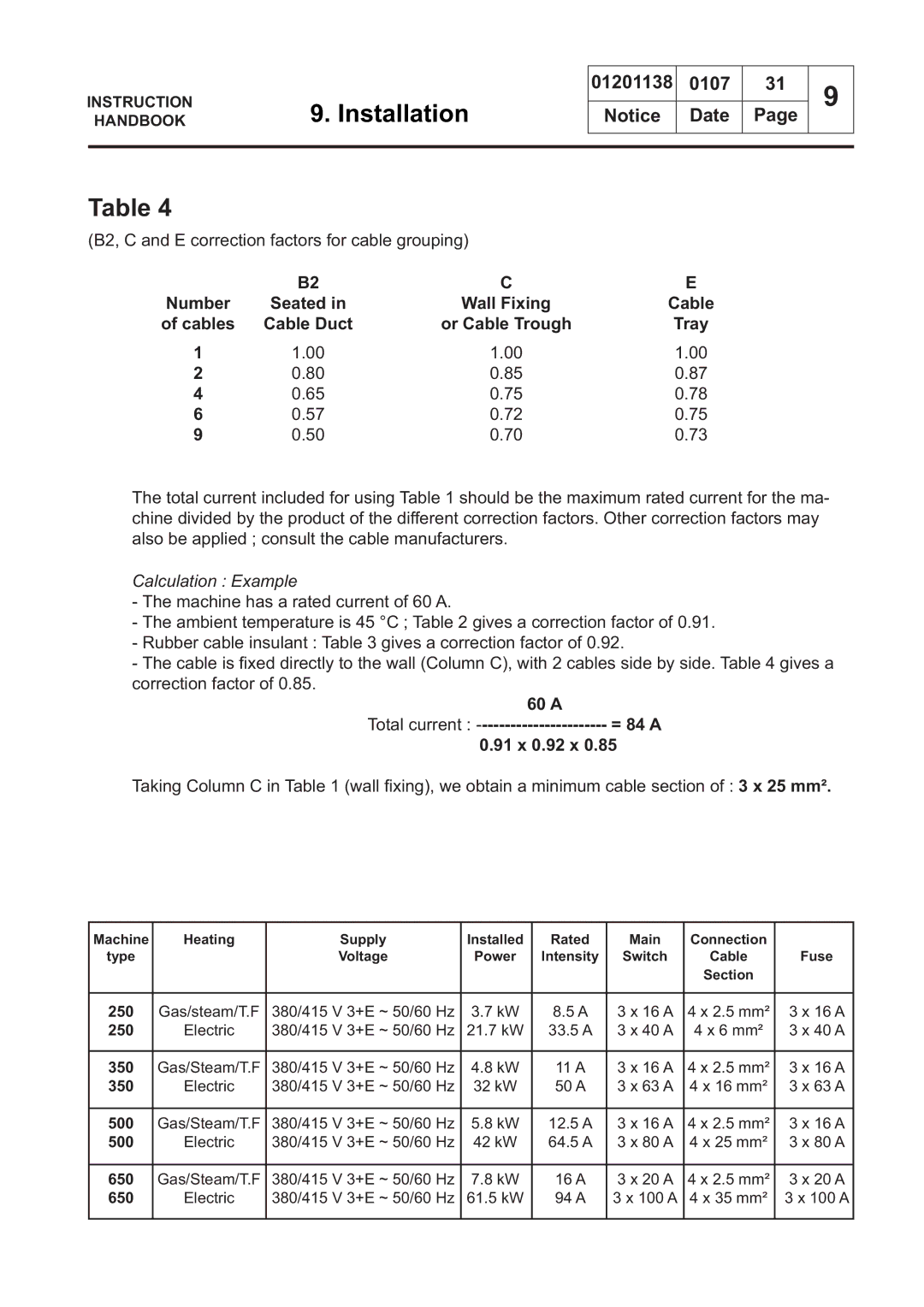
Table 4
(B2, C and E correction factors for cable grouping)
| B2 | C | E |
Number | Seated in | Wall Fixing | Cable |
of cables | Cable Duct | or Cable Trough | Tray |
1 | 1.00 | 1.00 | 1.00 |
2 | 0.80 | 0.85 | 0.87 |
4 | 0.65 | 0.75 | 0.78 |
6 | 0.57 | 0.72 | 0.75 |
9 | 0.50 | 0.70 | 0.73 |
The total current included for using Table 1 should be the maximum rated current for the ma- chine divided by the product of the different correction factors. Other correction factors may also be applied ; consult the cable manufacturers.
Calculation : Example
-The machine has a rated current of 60 A.
-The ambient temperature is 45 °C ; Table 2 gives a correction factor of 0.91.
-Rubber cable insulant : Table 3 gives a correction factor of 0.92.
-The cable is fi xed directly to the wall (Column C), with 2 cables side by side. Table 4 gives a correction factor of 0.85.
| 60 A |
Total current : | |
| 0.91 x 0.92 x 0.85 |
Taking Column C in Table 1 (wall fi xing), we obtain a minimum cable section of : 3 x 25 mm².
Machine | Heating | Supply | Installed | Rated | Main | Connection |
|
type |
| Voltage | Power | Intensity | Switch | Cable | Fuse |
|
|
|
|
|
| Section |
|
|
|
|
|
|
|
|
|
250 | Gas/steam/T.F | 380/415 V 3+E ~ 50/60 Hz | 3.7 kW | 8.5 A | 3 x 16 A | 4 x 2.5 mm² | 3 x 16 A |
250 | Electric | 380/415 V 3+E ~ 50/60 Hz | 21.7 kW | 33.5 A | 3 x 40 A | 4 x 6 mm² | 3 x 40 A |
|
|
|
|
|
|
|
|
350 | Gas/Steam/T.F | 380/415 V 3+E ~ 50/60 Hz | 4.8 kW | 11 A | 3 x 16 A | 4 x 2.5 mm² | 3 x 16 A |
350 | Electric | 380/415 V 3+E ~ 50/60 Hz | 32 kW | 50 A | 3 x 63 A | 4 x 16 mm² | 3 x 63 A |
|
|
|
|
|
|
|
|
500 | Gas/Steam/T.F | 380/415 V 3+E ~ 50/60 Hz | 5.8 kW | 12.5 A | 3 x 16 A | 4 x 2.5 mm² | 3 x 16 A |
500 | Electric | 380/415 V 3+E ~ 50/60 Hz | 42 kW | 64.5 A | 3 x 80 A | 4 x 25 mm² | 3 x 80 A |
|
|
|
|
|
|
|
|
650 | Gas/Steam/T.F | 380/415 V 3+E ~ 50/60 Hz | 7.8 kW | 16 A | 3 x 20 A | 4 x 2.5 mm² | 3 x 20 A |
650 | Electric | 380/415 V 3+E ~ 50/60 Hz | 61.5 kW | 94 A | 3 x 100 A | 4 x 35 mm² | 3 x 100 A |
|
|
|
|
|
|
|
|