Safety Information | Product Overview |
|
|
Installation
Diagnostics
Options and Accessories
Specification
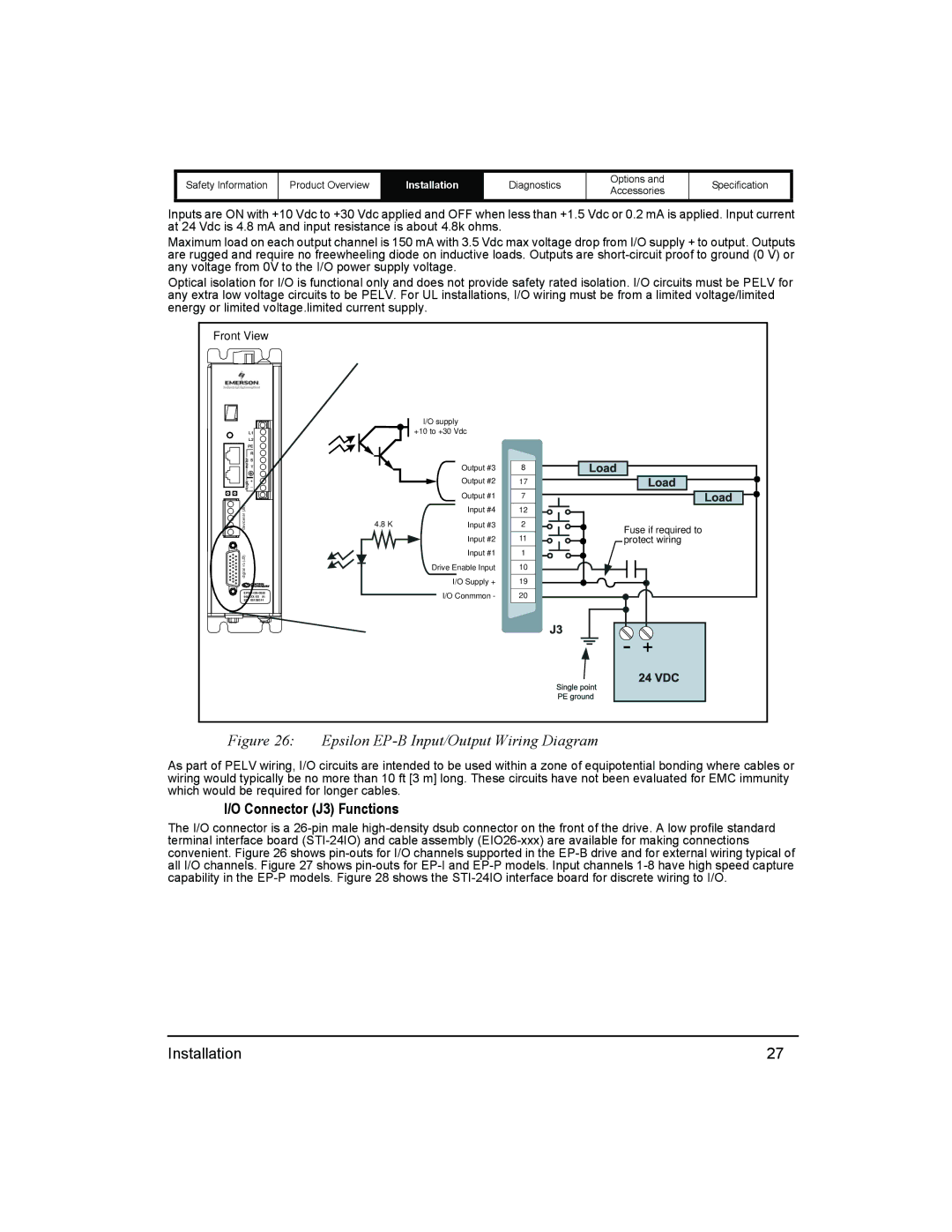
Inputs are ON with +10 Vdc to +30 Vdc applied and OFF when less than +1.5 Vdc or 0.2 mA is applied. Input current at 24 Vdc is 4.8 mA and input resistance is about 4.8k ohms.
Maximum load on each output channel is 150 mA with 3.5 Vdc max voltage drop from I/O supply + to output. Outputs are rugged and require no freewheeling diode on inductive loads. Outputs are
Optical isolation for I/O is functional only and does not provide safety rated isolation. I/O circuits must be PELV for any extra low voltage circuits to be PELV. For UL installations, I/O wiring must be from a limited voltage/limited energy or limited voltage.limited current supply.
Front View
| L1 |
| L2 |
| PE |
motor | R |
T | |
| S |
logic | + |
_ |
![]() digital i/o (J3)devicenet (J9)
digital i/o (J3)devicenet (J9)
| I/O supply |
|
| +10 to +30 Vdc |
|
| Output #3 | 8 |
| Output #2 | 17 |
| Output #1 | 7 |
| Input #4 | 12 |
4.8 K | Input #3 | 2 |
| Input #2 | 11 |
|
|
| Input #1 |
| 1 |
| Drive Enable Input | 10 | |||
|
|
|
|
| 19 |
|
| I/O Supply + |
| ||
|
| I/O Conmmon - | 20 | ||
|
| ||||
|
|
|
|
|
|
Fuse if required to protect wiring
Figure 26: Epsilon EP-B Input/Output Wiring Diagram
As part of PELV wiring, I/O circuits are intended to be used within a zone of equipotential bonding where cables or wiring would typically be no more than 10 ft [3 m] long. These circuits have not been evaluated for EMC immunity which would be required for longer cables.
I/O Connector (J3) Functions
The I/O connector is a
Installation | 27 |