Safety Information | Product Overview |
|
|
Installation
Diagnostics
Options and Accessories
Specification
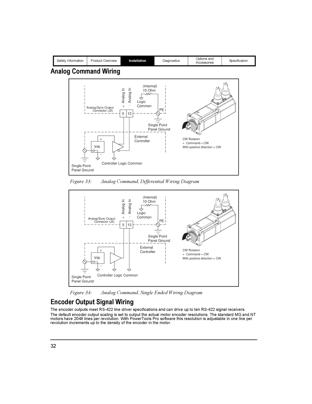
Analog Command Wiring
| In | In | (Internal) |
|
| 10 Ohm |
| ||
| Analog | Analog |
| |
| Logic |
| ||
Analog/Sync Output | + | - | Common |
|
Connector (J5) | 5 | 13 | PE |
|
|
|
| ||
|
|
| Single Point |
|
|
|
| Panel Ground |
|
+ |
|
| External | CW Rotation |
|
| Controller | ||
|
|
| + Command = CW | |
Vdc |
|
|
| |
|
|
| With positive direction = CW | |
_ |
|
|
|
|
Controller Logic Common |
| |||
Single Point |
|
|
|
|
Panel Ground |
|
|
|
|
Figure 33: Analog Command, Differential Wiring Diagram
|
| In | In | (Internal) |
|
|
| 10 Ohm |
| ||
|
| Analog | Analog |
| |
|
| Logic |
| ||
Analog/Sync Output | + | - | Common |
| |
| Connector (J5) | 5 | 13 | PE |
|
|
|
|
| ||
|
|
|
| Single Point |
|
|
|
|
| Panel Ground |
|
| + |
|
| External | CW Rotation |
|
|
| Controller | ||
|
|
|
| + Command = CW | |
| Vdc |
|
|
| |
|
|
|
| With positive direction = CW | |
| _ |
|
|
|
|
Single Point | Controller Logic Common |
| |||
|
|
|
|
| |
Panel Ground |
|
|
|
|
|
Figure 34: Analog Command, Single Ended Wiring Diagram
Encoder Output Signal Wiring
The encoder outputs meet
The default encoder output scaling is set to output the actual motor encoder resolutions. The standard MG and NT motors have 2048 lines per revolution. With PowerTools Pro software this resolution is adjustable in one line per revolution increments up to the density of the encoder in the motor.
32