Safety Information | Product Overview |
|
|
Installation
Diagnostics
Options and Accessories
Specification
1 ∝s Minimum |
|
|
|
|
|
|
|
|
|
|
|
|
|
|
|
|
|
|
|
| 1 | ∝s Minimum | |||||||
|
|
|
|
|
|
|
|
|
|
|
|
|
|
|
|
|
|
|
|
|
|
|
|
|
|
|
| ||
|
|
|
|
|
|
|
|
|
|
|
|
|
|
|
|
|
|
|
|
|
|
|
|
|
|
|
| 500 ns Minimum | |
|
|
|
|
|
|
|
|
|
|
|
|
|
|
|
|
|
|
|
|
|
|
|
|
|
|
|
|
| |
Motion occurs |
|
|
|
|
|
|
|
|
|
|
|
|
|
|
|
|
|
|
|
|
|
|
| CW Pulse | |||||
|
|
|
|
|
|
|
|
|
|
|
|
|
|
|
|
|
|
|
|
|
|
| |||||||
on falling edge |
|
|
|
|
|
|
|
|
|
|
|
|
|
|
|
|
|
|
| ||||||||||
|
|
|
|
|
|
|
|
|
|
|
|
|
|
|
|
|
|
|
|
|
|
|
|
|
|
|
|
| |
|
|
|
|
| CW |
|
|
| CCW | CCW Pulse | |||||||||||||||||||
| |||||||||||||||||||||||||||||
|
|
|
|
|
|
|
|
|
|
|
|
|
|
|
|
|
|
|
|
|
|
| |||||||
|
|
|
|
|
|
|
|
|
|
|
|
|
|
|
|
|
|
|
|
|
|
|
|
|
|
|
|
| |
|
|
|
|
|
|
|
| Sinking | |||||||||||||||||||||
|
|
|
|
|
|
|
|
| |||||||||||||||||||||
|
|
|
|
|
| Outputs (typ) |
| ||||||||||||||||||||||
|
|
|
|
|
|
|
|
|
|
|
|
|
|
|
|
|
|
|
|
|
|
|
|
|
|
|
|
|
|
|
|
|
|
|
|
|
|
|
|
|
|
|
|
|
|
|
|
|
|
|
|
|
|
|
|
|
|
|
|
|
|
|
|
|
|
|
|
|
|
|
|
|
|
|
|
|
|
|
|
|
|
|
|
|
|
|
|
|
|
|
|
|
|
|
|
|
|
|
|
|
|
|
|
|
|
|
|
|
|
|
|
|
|
|
|
|
|
|
|
|
|
|
|
|
|
|
|
|
|
|
|
|
|
|
|
|
|
|
|
|
|
|
|
|
|
|
|
|
|
|
|
|
|
|
|
|
|
|
|
|
|
|
|
|
|
|
|
|
|
|
|
|
|
|
|
|
|
|
|
|
|
|
|
|
|
|
|
|
|
|
|
|
|
|
|
|
|
|
|
|
|
|
|
|
|
|
|
|
|
|
|
|
|
|
|
|
|
|
|
|
|
|
|
|
|
|
|
|
|
|
|
|
|
|
|
|
|
|
|
|
|
|
|
|
|
|
|
|
|
|
|
|
|
|
|
|
|
|
|
|
|
|
|
|
|
|
|
|
|
|
|
|
|
|
|
|
|
|
|
|
|
|
|
|
|
|
|
|
|
|
|
|
|
|
|
|
|
|
|
|
|
|
|
|
|
|
|
|
|
|
|
|
|
|
|
|
|
|
|
|
|
|
|
|
|
|
|
|
|
|
|
|
|
|
|
|
|
|
|
|
|
|
|
|
|
|
|
|
|
|
|
|
|
|
|
|
|
|
|
|
|
|
|
|
|
|
|
|
|
|
|
|
|
|
|
|
|
|
|
|
|
|
|
|
|
|
|
|
|
![]()
![]() Drive
Drive
Analog/Sync Output Connector
(J5)
Pulse Direction
4 |
| 12 | 8 |
|
|
|
|
CW Pulse
CCW Pulse
Shield connected to connector shell
logic
10common
Ohm ![]()
PE
Single Point
Panel Ground
Common isolated from other sources
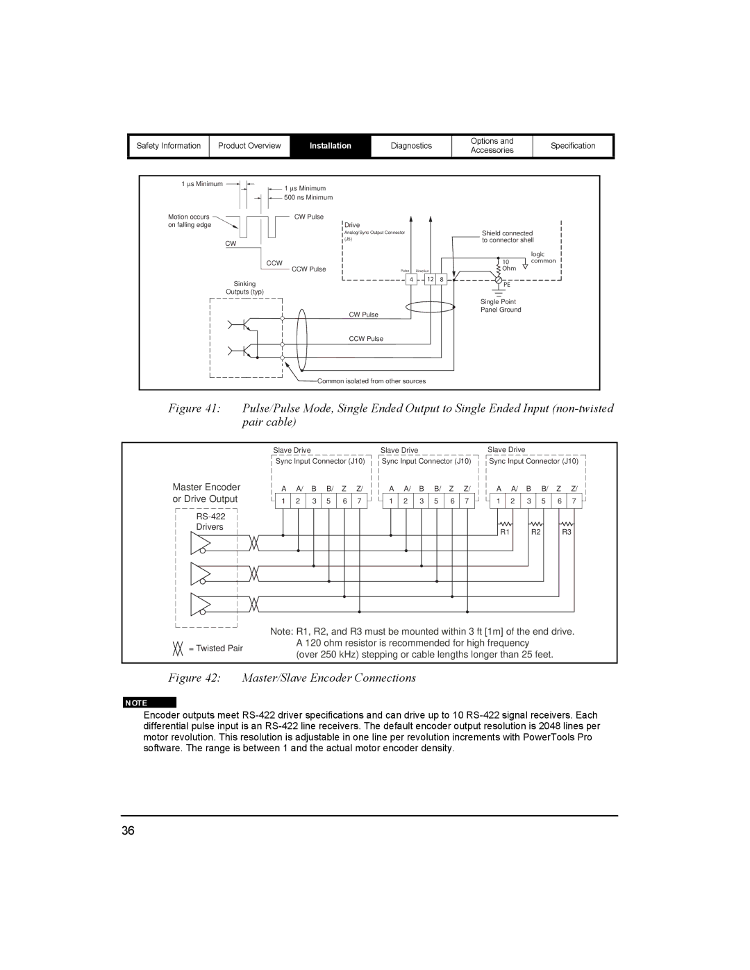
Figure 41: Pulse/Pulse Mode, Single Ended Output to Single Ended Input (non-twisted pair cable)
|
|
|
|
|
|
|
|
|
|
|
|
|
|
|
|
|
|
|
|
| Slave Drive |
|
|
|
| Slave Drive |
|
|
|
| ||
|
|
|
|
|
|
|
|
|
|
|
|
|
|
|
|
|
|
|
|
| Sync Input Connector | (J10) | Sync Input Connector (J10) | |||||||||
Master Encoder | A | A/ | B | B/ | Z | Z/ | A | A/ | B | B/ | Z | Z/ | ||||||||||||||||||||
or Drive Output | 1 | 2 | 3 | 5 | 6 | 7 | 1 | 2 | 3 | 5 | 6 | 7 | ||||||||||||||||||||
|
|
|
|
|
|
|
|
|
|
|
|
|
|
|
|
|
|
|
|
|
|
|
|
|
|
|
|
|
|
|
|
|
Drivers
Slave Drive
Sync Input Connector (J10)
A A/ B B/ Z Z/
1 2 3 5 6 7
R1 R2 R3
Note: R1, R2, and R3 must be mounted within 3 ft [1m] of the end drive.
= Twisted Pair
A 120 ohm resistor is recommended for high frequency (over 250 kHz) stepping or cable lengths longer than 25 feet.
Figure 42: Master/Slave Encoder Connections
Encoder outputs meet
36