Safety Information | Product Overview |
|
|
Installation
Diagnostics
Options and Accessories
Specification
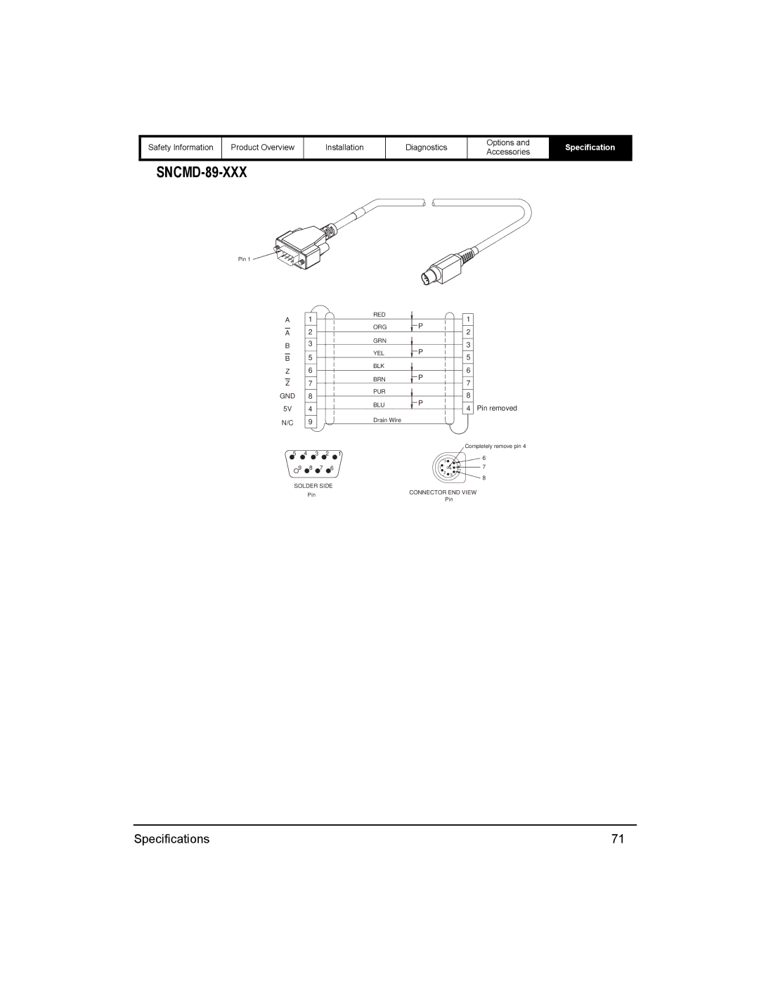
SNCMD-89-XXX
Pin 1 ![]()
A 1
A2
B3
B 5
Z6
Z 7
GND 8
5V 4
N/C 9
RED
ORG P
GRN
YEL P
BLK
BRN P
PUR
BLU ![]() P
P
Drain Wire
1
2
3
5
6
7
8
4 Pin removed
Completely remove pin 4
5 | 4 | 3 | 2 | 1 |
| 6 |
|
|
|
| 3 |
| |
|
|
|
|
| 7 | |
9 | 8 | 7 | 6 | 1 | 4 | |
|
|
|
| 2 | 5 | 8 |
|
|
|
|
|
|
SOLDER SIDE
Pin | CONNECTOR END VIEW | |
Pin | ||
|
Specifications | 71 |