Safety Information | Product Overview |
|
|
Installation
Diagnostics
Options and Accessories
Specification
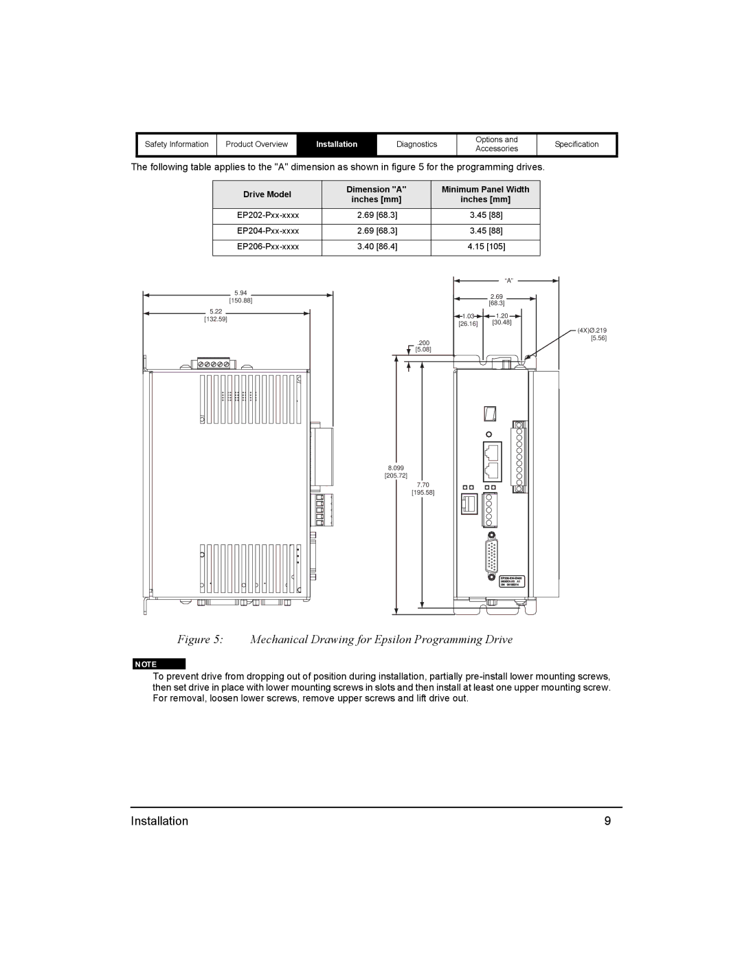
The following table applies to the "A" dimension as shown in figure 5 for the programming drives.
Drive Model | Dimension "A" | Minimum Panel Width | |
inches [mm] | inches [mm] | ||
| |||
2.69 [68.3] | 3.45 [88] | ||
|
|
| |
2.69 [68.3] | 3.45 [88] | ||
|
|
| |
3.40 [86.4] | 4.15 [105] | ||
|
|
|
5.94
[150.88]
5.22
[132.59]
“A”
2.69
[68.3]
![]() 1.03
1.03![]()
![]() 1.20
1.20 ![]()
[26.16] [30.48]
.200
[5.08]
(4X)Ø.219
[5.56]
8.099
[205.72]
7.70
[195.58]
Figure 5: Mechanical Drawing for Epsilon Programming Drive
To prevent drive from dropping out of position during installation, partially
Installation | 9 |