Safety Information | Product Overview |
|
|
Installation
Diagnostics
Options and Accessories
Specification
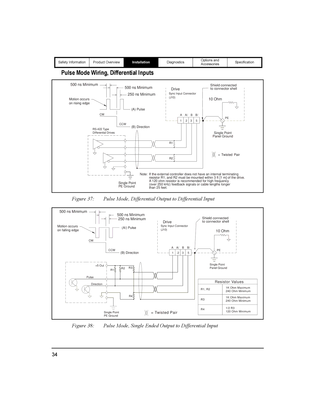
Pulse Mode Wiring, Differential Inputs
500 ns Minimum
![]() 500 ns Minimum
500 ns Minimum
250 ns Minimum
Motion occurs on rising edge
(A) Pulse
CW
CCW
(B) Direction
Differential Drives
|
|
| Shield connected |
Drive |
|
| to connector shell |
Sync Input Connector | |||
(J10) |
|
| 10 Ohm |
|
|
| |
A | A/ | B | B/ |
1 | 2 | 3 | PE |
5 | |||
Single Point
Panel Ground
R1 ![]()
R2 ![]()
= Twisted Pair
Single Point PE Ground
Note: If the external controller does not have an internal terminating resistor R1, and R2 must be mounted within 3 ft [1 m] of the drive. A 120 ohm resistor is recommended for high frequency
(over 250 kHz) feedback signals or cable lengths longer than 25 feet.
Figure 37: Pulse Mode, Differential Output to Differential Input
500 ns Minimum |
| 500 ns Minimum |
|
|
|
|
|
| |
|
|
|
|
| Shield connected | ||||
|
| 250 ns Minimum | Drive |
|
| ||||
Motion occurs |
|
|
|
|
| to connector shell | |||
| (A/) Pulse | Sync Input Connector |
|
| |||||
on falling edge |
| (J10) |
|
|
|
| 10 Ohm | ||
|
|
|
|
|
|
| |||
|
|
|
|
|
|
|
| ||
CW |
|
|
|
|
|
|
|
|
|
| CCW |
|
| A | A/ | B | B/ |
| PE |
| (B) Direction | 1 | 2 | 3 | 5 |
| |||
|
|
|
| ||||||
+5 Out |
|
| R3 |
|
|
|
| Single Point | |
| R2 |
|
|
|
| Panel Ground | |||
| R1 |
|
|
|
| ||||
|
|
|
|
|
|
|
|
| |
Pulse |
|
|
|
|
|
|
|
|
|
Direction |
|
|
|
|
|
|
|
| Resistor Values |
|
|
|
|
|
|
|
| 1K Ohm Maximum | |
|
|
|
|
|
|
| R1, R2 | ||
|
|
|
|
|
|
| 240 Ohm Minimum | ||
|
|
|
|
|
|
|
|
| |
|
|
| R4 |
|
|
| R3 |
| 1K Ohm Maximum |
|
|
|
|
|
|
|
| ||
|
|
|
|
|
|
|
| 240 Ohm Minimum | |
|
|
|
|
|
|
|
|
| |
|
|
|
|
|
|
| R4 |
| 1/2 R3 |
| Single Point |
| = Twisted Pair |
|
| 120 Ohm Minimum | |||
|
|
|
|
| |||||
| PE Ground |
|
|
|
|
|
|
| |
Figure 38: Pulse Mode, Single Ended Output to Differential Input
34