Safety Information | Product Overview |
|
|
Installation
Diagnostics
Options and Accessories
Specification
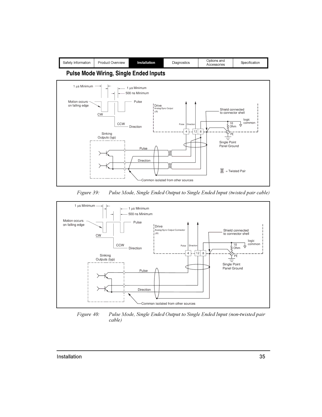
Pulse Mode Wiring, Single Ended Inputs
1 ∝s Minimum | 1 | ∝s Minimum |
|
|
|
|
|
|
|
|
| ||
| 500 ns Minimum |
|
|
|
| |
Motion occurs |
| Pulse |
|
|
|
|
on falling edge |
| Drive |
|
|
|
|
|
| Analog/Sync Output |
|
| Shield connected | |
|
| (J5) |
|
| ||
| CW |
|
| to connector shell | ||
|
|
|
| |||
|
|
|
|
|
| |
|
|
|
|
|
| logic |
| CCW | Pulse | Direction | 10 | common | |
|
| Direction |
|
| Ohm |
|
| Sinking |
| 4 | 12 | 8 |
|
|
|
|
| PE |
| |
| Outputs (typ) |
|
|
|
|
|
|
|
|
|
| Single Point |
|
|
| Pulse |
|
| Panel Ground |
|
|
|
|
|
|
| |
|
| Direction |
|
|
|
|
|
|
|
|
| = Twisted Pair | |
|
| Common isolated from other sources |
|
|
| |
Figure 39: Pulse Mode, Single Ended Output to Single Ended Input (twisted pair cable)
1 ∝s Minimum | ∝s Minimum |
|
|
|
|
1 |
|
|
|
| |
500 ns Minimum |
|
|
|
| |
Motion occurs | Pulse |
|
|
|
|
on falling edge |
|
|
|
| |
Drive |
|
|
|
| |
|
|
| Shield connected | ||
| Analog/Sync Output Connector |
|
| ||
CW | (J5) |
|
| to connector shell | |
|
|
|
|
| |
|
|
|
|
| logic |
CCW | Pulse | Direction | 10 | common | |
Direction |
|
| Ohm |
| |
Sinking |
| 4 | 12 | 8 |
|
|
|
| PE |
| |
Outputs (typ) |
|
|
|
|
|
|
|
|
| Single Point |
|
| Pulse |
|
| Panel Ground |
|
|
|
|
|
| |
| Direction |
|
|
|
|
| Common isolated from other sources |
|
|
| |
Figure 40: Pulse Mode, Single Ended Output to Single Ended Input (non-twisted pair cable)
Installation | 35 |