Safety Information | Product Overview |
|
|
Installation
Diagnostics
Options and Accessories
Specification
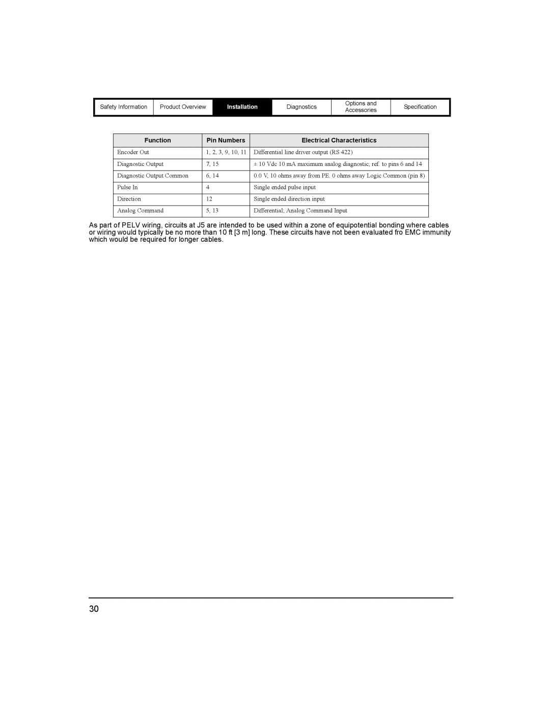
Function | Pin Numbers | Electrical Characteristics |
Encoder Out | 1, 2, 3, 9, 10, 11 | Differential line driver output (RS 422) |
|
|
|
Diagnostic Output | 7, 15 | ± 10 Vdc 10 mA maximum analog diagnostic, ref. to pins 6 and 14 |
|
|
|
Diagnostic Output Common | 6, 14 | 0.0 V, 10 ohms away from PE. 0 ohms away Logic Common (pin 8) |
|
|
|
Pulse In | 4 | Single ended pulse input |
|
|
|
Direction | 12 | Single ended direction input |
|
|
|
Analog Command | 5, 13 | Differential; Analog Command Input |
|
|
|
As part of PELV wiring, circuits at J5 are intended to be used within a zone of equipotential bonding where cables or wiring would typically be no more than 10 ft [3 m] long. These circuits have not been evaluated fro EMC immunity which would be required for longer cables.
30