Safety Information | Product Overview |
|
|
Installation
Diagnostics
Options and Accessories
Specification
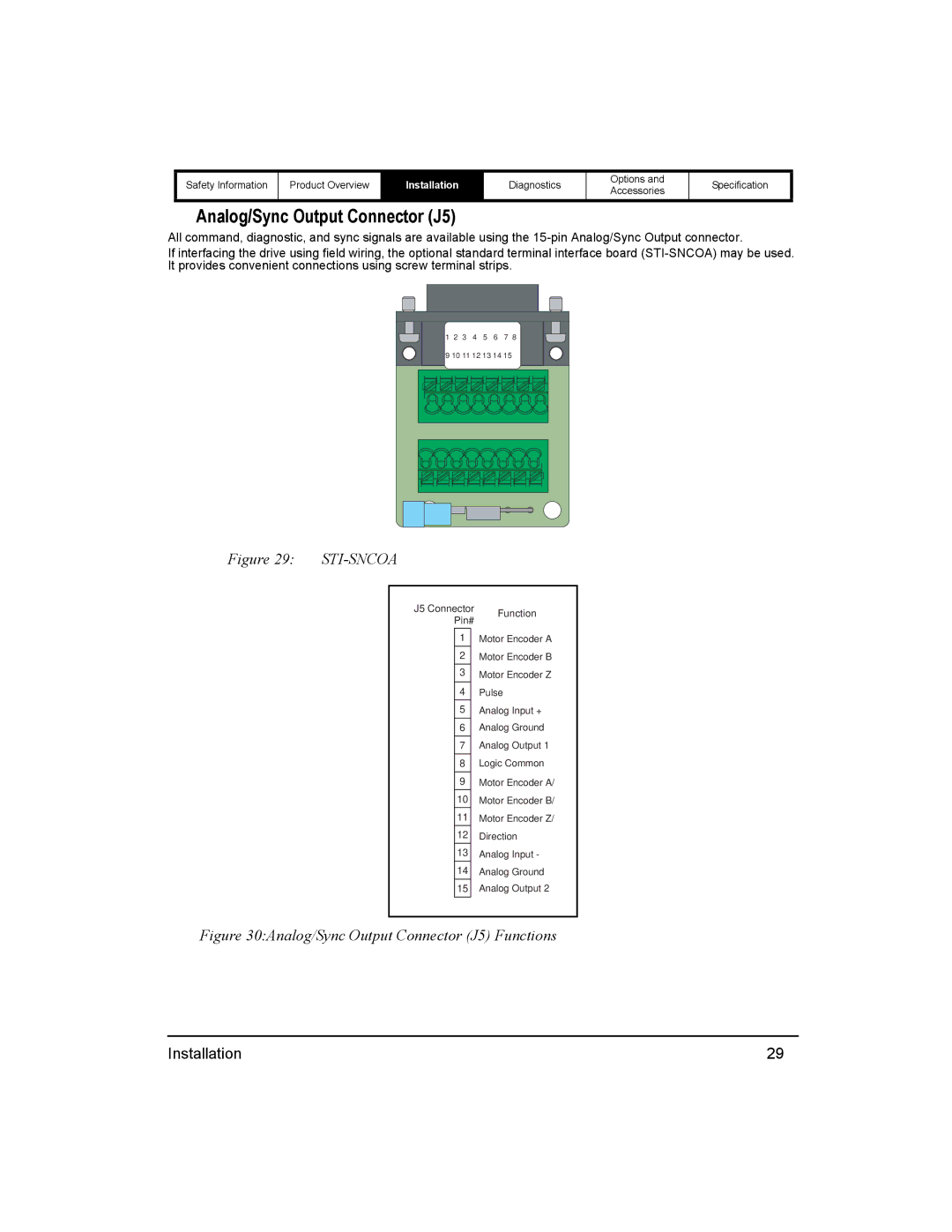
Analog/Sync Output Connector (J5)
All command, diagnostic, and sync signals are available using the
If interfacing the drive using field wiring, the optional standard terminal interface board
1 2 3 4 5 6 7 8
9 10 11 12 13 14 15
Figure 29: |
|
| |||
|
|
|
| ||
|
| J5 Connector | Function | ||
|
|
| Pin# | ||
|
|
|
| ||
|
|
| 1 |
| Motor Encoder A |
|
|
| 2 |
| Motor Encoder B |
|
|
| 3 |
| Motor Encoder Z |
|
|
| 4 |
| Pulse |
|
|
| 5 |
| Analog Input + |
|
|
| 6 |
| Analog Ground |
|
|
| 7 |
| Analog Output 1 |
|
|
| 8 |
| Logic Common |
|
|
| 9 |
| Motor Encoder A/ |
|
|
| 10 |
| Motor Encoder B/ |
|
|
| 11 |
| Motor Encoder Z/ |
|
|
| 12 |
| Direction |
|
|
| 13 |
| Analog Input - |
|
|
| 14 |
| Analog Ground |
|
|
| 15 |
| Analog Output 2 |
|
|
|
|
|
|
Figure 30:Analog/Sync Output Connector (J5) Functions
Installation | 29 |