Safety Information | Product Overview |
|
|
Installation
Diagnostics
Options and Accessories
Specification
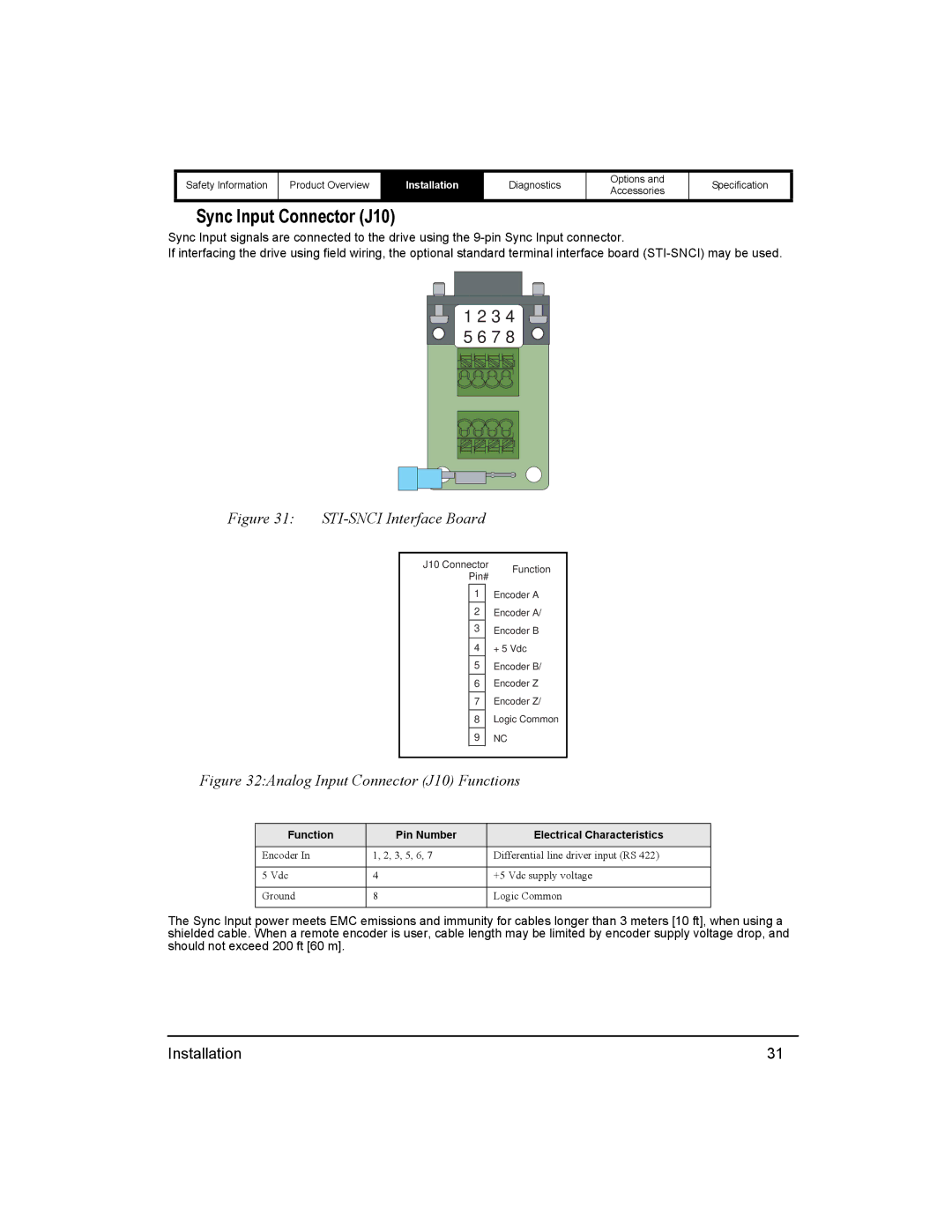
Sync Input Connector (J10)
Sync Input signals are connected to the drive using the
If interfacing the drive using field wiring, the optional standard terminal interface board
1 2 3 4
5 6 7 8
Figure 31: |
|
| |||
|
|
|
| ||
|
| J10 Connector | Function | ||
|
|
| Pin# | ||
|
|
|
| ||
|
|
| 1 |
| Encoder A |
|
|
| 2 |
| Encoder A/ |
|
|
| 3 |
| Encoder B |
|
|
| 4 |
| + 5 Vdc |
|
|
| 5 |
| Encoder B/ |
|
|
| 6 |
| Encoder Z |
|
|
| 7 |
| Encoder Z/ |
|
|
| 8 |
| Logic Common |
|
|
| 9 |
| NC |
|
|
|
|
|
|
Figure 32:Analog Input Connector (J10) Functions
Function | Pin Number | Electrical Characteristics |
Encoder In | 1, 2, 3, 5, 6, 7 | Differential line driver input (RS 422) |
|
|
|
5 Vdc | 4 | +5 Vdc supply voltage |
|
|
|
Ground | 8 | Logic Common |
|
|
|
The Sync Input power meets EMC emissions and immunity for cables longer than 3 meters [10 ft], when using a shielded cable. When a remote encoder is user, cable length may be limited by encoder supply voltage drop, and should not exceed 200 ft [60 m].
Installation | 31 |