Safety Information | Product Overview | Installation | Diagnostics |
| Options and | Specification | |||
| Accessories | ||||||||
|
|
|
|
|
|
|
| ||
|
|
|
|
|
|
|
| XV | |
L1 |
|
|
|
|
|
| Black - | Motor | |
|
|
|
|
|
|
|
|
| |
L2 |
|
|
|
| A1 | A2 |
|
|
|
PE |
|
|
|
|
|
|
| ||
R |
|
|
|
|
|
|
|
|
|
S |
|
|
|
|
|
|
|
|
|
motor T |
|
|
|
|
|
|
|
|
|
+ |
|
|
|
|
|
|
|
|
|
logic _ |
|
|
|
|
|
|
| C |
|
|
|
| Customer |
|
|
|
|
| |
|
|
|
| K1 |
|
| B |
| |
|
|
| supplied drive |
|
|
|
| A | Internal |
| Output #3 | 8 | enable contact |
|
|
|
| ||
|
|
|
|
|
| ||||
|
|
|
|
|
|
| to Motor | ||
| Drive Enable | 10 |
|
|
|
|
|
| |
|
| 2 Amp |
|
|
|
|
| ||
|
|
|
|
|
|
|
|
| |
|
| 19 |
| Fuse |
|
|
|
|
|
(J3) | I/O Supply | 1 Amp |
| 14 | 11 | Red + |
|
| |
digital i/o |
|
|
| Relay: |
| ||||
I/O Common | 20 | Fuse |
|
|
| ||||
|
|
| Model# |
|
|
| |||
|
|
|
|
|
|
| |||
|
|
|
|
|
|
|
|
| |
SN 0610E014 |
|
|
|
|
|
|
|
|
|
| J3 |
| - | + |
|
|
| Connected to |
|
|
|
|
|
|
| grounded |
| ||
|
| Single point |
|
|
|
|
| mounting panel. |
|
|
|
| 24 VDC |
|
|
|
|
| |
|
| PE ground |
|
|
|
|
|
| |
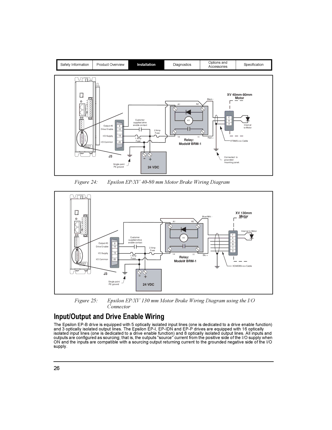
Figure 24: Epsilon EP/XV 40-80 mm Motor Brake Wiring Diagram
|
|
|
|
|
|
|
|
| XV 130mm |
L1 |
|
|
|
|
|
| Blue/Wht- | - | Motor |
L2 |
|
|
|
| A1 | A2 |
|
|
|
PE |
|
|
|
|
|
|
| ||
R |
|
|
|
|
|
|
|
|
|
S |
|
|
|
|
|
|
|
|
|
motor T |
|
|
|
|
|
|
|
|
|
+ |
|
|
|
|
|
|
|
| Internal to Motor |
logic _ |
|
|
|
|
|
|
|
| F |
|
|
| Customer |
|
|
|
|
| |
|
|
|
| K1 |
|
|
| E | |
|
|
| supplied drive |
|
|
|
|
| A |
| Output #3 | 8 | enable contact |
|
|
|
|
| |
|
|
|
|
|
| B | |||
| Drive Enable | 10 |
|
|
|
|
|
| |
|
| 2 Amp |
|
|
|
| C | ||
|
|
|
|
|
|
|
| ||
| I/O Supply | 19 |
| Fuse |
|
|
|
| D |
(J3) | 1 Amp |
| 14 | 11 | Blu + |
|
| ||
digital i/o |
|
|
| Relay: |
|
|
| ||
I/O Common | 20 | Fuse |
|
|
|
|
| ||
|
|
| Model# |
|
|
| |||
|
|
|
|
|
|
| |||
|
|
|
|
|
|
|
|
| |
SN 0610E014 |
|
|
|
|
|
|
|
| |
|
|
|
|
|
|
|
|
| |
| J3 |
| - | + |
|
|
|
|
|
|
|
|
|
|
|
|
| ||
|
| Single point |
| 24 VDC |
|
|
|
|
|
|
| PE ground |
|
|
|
|
|
| |
Figure 25: Epsilon EP/XV 130 mm Motor Brake Wiring Diagram using the I/O Connector
Input/Output and Drive Enable Wiring
The Epsilon
26