Safety Information | Product Overview |
|
|
Installation
Diagnostics
Options and Accessories
Specification
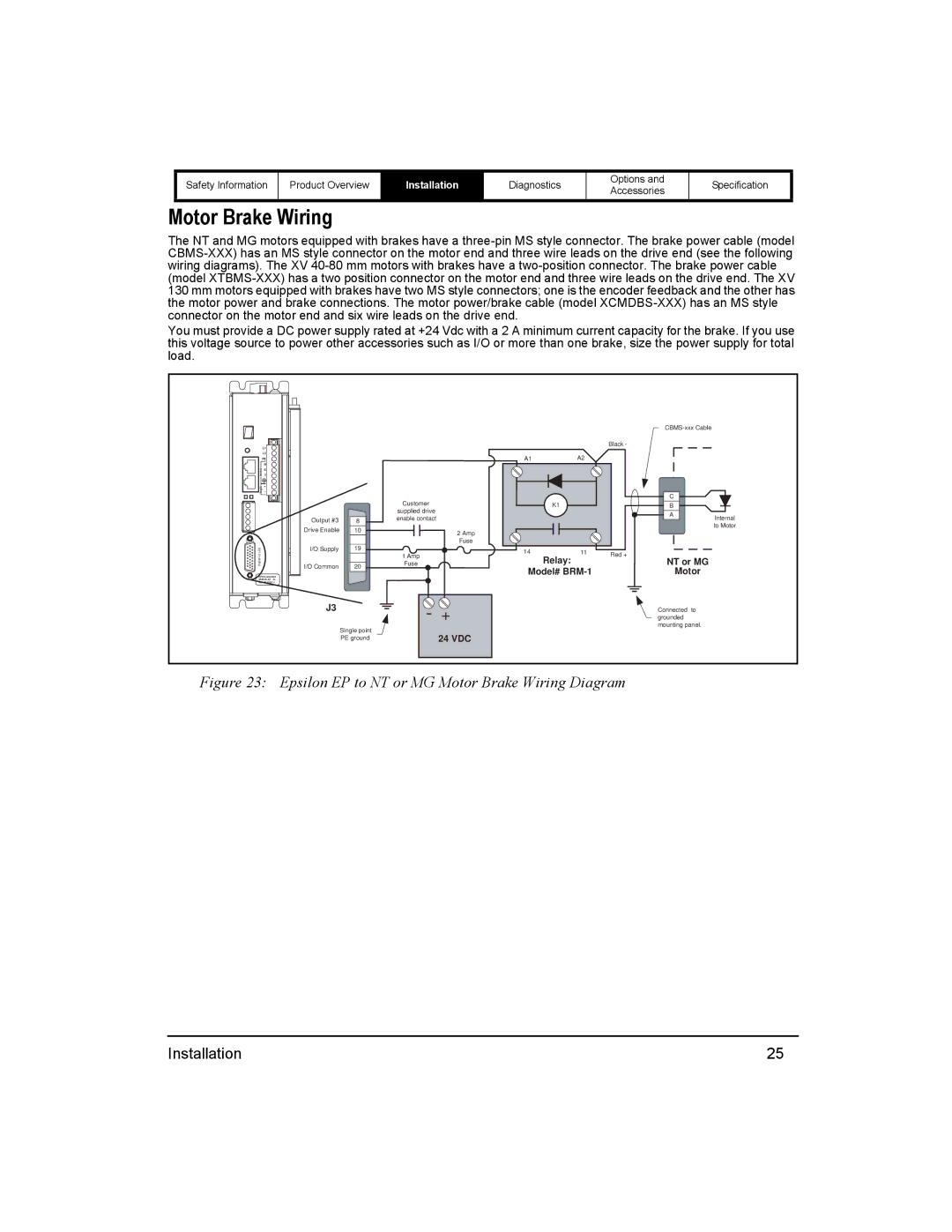
Motor Brake Wiring
The NT and MG motors equipped with brakes have a
You must provide a DC power supply rated at +24 Vdc with a 2 A minimum current capacity for the brake. If you use this voltage source to power other accessories such as I/O or more than one brake, size the power supply for total load.
|
|
|
|
|
|
|
| |
L1 |
|
|
|
|
| Black - |
|
|
|
|
|
|
|
|
|
| |
L2 |
|
|
| A1 | A2 |
|
|
|
PE |
|
|
|
|
|
| ||
R |
|
|
|
|
|
|
|
|
S |
|
|
|
|
|
|
|
|
motor T |
|
|
|
|
|
|
|
|
+ |
|
|
|
|
|
|
|
|
logic _ |
|
|
|
|
|
| C |
|
|
|
| Customer |
|
|
|
| |
|
|
| K1 |
|
| B |
| |
|
|
| supplied drive |
|
|
| A | Internal |
| Output #3 | 8 | enable contact |
|
|
| ||
|
|
|
|
| ||||
|
|
|
|
|
| to Motor | ||
| Drive Enable | 10 |
|
|
|
|
| |
|
| 2 Amp |
|
|
|
| ||
|
|
|
|
|
|
|
| |
|
| 19 |
| Fuse |
|
|
|
|
(J3) | I/O Supply | 1 Amp | 14 | 11 | Red + |
|
| |
digital i/o |
|
| Relay: |
| NT or MG |
| ||
I/O Common | 20 | Fuse |
|
|
| |||
|
| Model# |
| Motor |
| |||
|
|
|
|
| ||||
|
|
|
|
|
|
|
| |
SN 0610E014 |
|
|
|
|
|
|
|
|
| J3 |
| - | + |
|
| Connected to |
|
|
|
|
|
| grounded |
| ||
|
| Single point |
|
|
|
| mounting panel. |
|
|
|
| 24 VDC |
|
|
|
| |
|
| PE ground |
|
|
|
|
| |
Figure 23: Epsilon EP to NT or MG Motor Brake Wiring Diagram |
|
| ||||||
Installation | 25 |