Emerson Process Management 1500 manual Optional Transmitter Configuration, Contents

Models: 1500

1 146
Download 146 pages 48.94 Kb
Page 4
Image 4

Contents

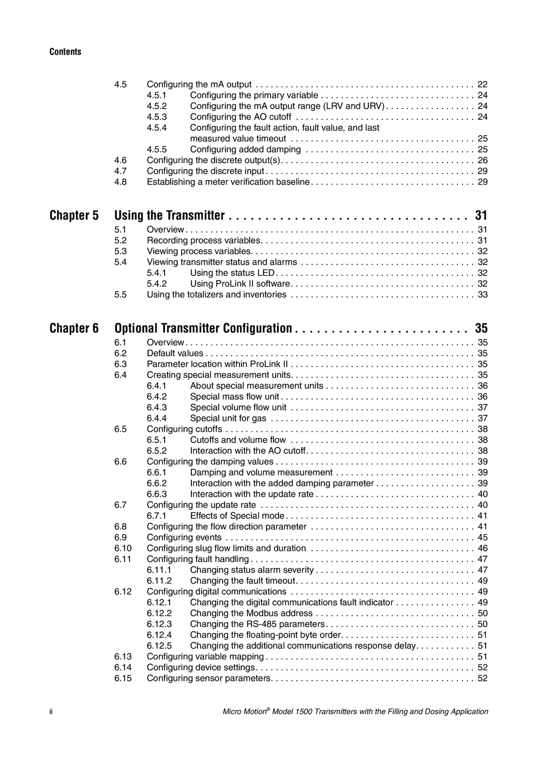
4.5 Configuring the mA output . . . . . . . . . . . . . . . . . . . . . . . . . . . . . . . . . . . . . . . . . . . . 22

4.5.1 Configuring the primary variable . . . . . . . . . . . . . . . . . . . . . . . . . . . . . . . 24

4.5.2 Configuring the mA output range (LRV and URV) . . . . . . . . . . . . . . . . . . 24

4.5.3 Configuring the AO cutoff . . . . . . . . . . . . . . . . . . . . . . . . . . . . . . . . . . . . 24

4.5.4Configuring the fault action, fault value, and last

measured value timeout . . . . . . . . . . . . . . . . . . . . . . . . . . . . . . . . . . . . . 25

4.5.5 Configuring added damping . . . . . . . . . . . . . . . . . . . . . . . . . . . . . . . . . . 25

4.6 Configuring the discrete output(s). . . . . . . . . . . . . . . . . . . . . . . . . . . . . . . . . . . . . . . 26

4.7 Configuring the discrete input . . . . . . . . . . . . . . . . . . . . . . . . . . . . . . . . . . . . . . . . . . 29

4.8 Establishing a meter verification baseline . . . . . . . . . . . . . . . . . . . . . . . . . . . . . . . . . 29

Chapter 5 Using the Transmitter . . . . . . . . . . . . . . . . . . . . . . . . . . . . . . . . . 31

5.1 Overview . . . . . . . . . . . . . . . . . . . . . . . . . . . . . . . . . . . . . . . . . . . . . . . . . . . . . . . . . . 31

5.2 Recording process variables. . . . . . . . . . . . . . . . . . . . . . . . . . . . . . . . . . . . . . . . . . . 31

5.3 Viewing process variables. . . . . . . . . . . . . . . . . . . . . . . . . . . . . . . . . . . . . . . . . . . . . 32

5.4 Viewing transmitter status and alarms . . . . . . . . . . . . . . . . . . . . . . . . . . . . . . . . . . . 32

5.4.1 Using the status LED . . . . . . . . . . . . . . . . . . . . . . . . . . . . . . . . . . . . . . . . 32

5.4.2 Using ProLink II software. . . . . . . . . . . . . . . . . . . . . . . . . . . . . . . . . . . . . 32

5.5 Using the totalizers and inventories . . . . . . . . . . . . . . . . . . . . . . . . . . . . . . . . . . . . . 33

Chapter 6 Optional Transmitter Configuration

35

6.1 Overview . . . . . . . . . . . . . . . . . . . . . . . . . . . . . . . . . . . . . . . . . . . . . . . . . . . . . . . . . . 35

6.2 Default values . . . . . . . . . . . . . . . . . . . . . . . . . . . . . . . . . . . . . . . . . . . . . . . . . . . . . . 35

6.3 Parameter location within ProLink II . . . . . . . . . . . . . . . . . . . . . . . . . . . . . . . . . . . . . 35

6.4 Creating special measurement units. . . . . . . . . . . . . . . . . . . . . . . . . . . . . . . . . . . . . 35

6.4.1 About special measurement units . . . . . . . . . . . . . . . . . . . . . . . . . . . . . . 36

6.4.2 Special mass flow unit . . . . . . . . . . . . . . . . . . . . . . . . . . . . . . . . . . . . . . . 36

6.4.3 Special volume flow unit . . . . . . . . . . . . . . . . . . . . . . . . . . . . . . . . . . . . . 37

6.4.4 Special unit for gas . . . . . . . . . . . . . . . . . . . . . . . . . . . . . . . . . . . . . . . . . 37

6.5 Configuring cutoffs . . . . . . . . . . . . . . . . . . . . . . . . . . . . . . . . . . . . . . . . . . . . . . . . . . 38

6.5.1 Cutoffs and volume flow . . . . . . . . . . . . . . . . . . . . . . . . . . . . . . . . . . . . . 38

6.5.2 Interaction with the AO cutoff. . . . . . . . . . . . . . . . . . . . . . . . . . . . . . . . . . 38

6.6 Configuring the damping values . . . . . . . . . . . . . . . . . . . . . . . . . . . . . . . . . . . . . . . . 39

6.6.1 Damping and volume measurement . . . . . . . . . . . . . . . . . . . . . . . . . . . . 39

6.6.2 Interaction with the added damping parameter . . . . . . . . . . . . . . . . . . . . 39

6.6.3 Interaction with the update rate . . . . . . . . . . . . . . . . . . . . . . . . . . . . . . . . 40

6.7 Configuring the update rate . . . . . . . . . . . . . . . . . . . . . . . . . . . . . . . . . . . . . . . . . . . 40

6.7.1 Effects of Special mode . . . . . . . . . . . . . . . . . . . . . . . . . . . . . . . . . . . . . . 41

6.8 Configuring the flow direction parameter . . . . . . . . . . . . . . . . . . . . . . . . . . . . . . . . . 41

6.9 Configuring events . . . . . . . . . . . . . . . . . . . . . . . . . . . . . . . . . . . . . . . . . . . . . . . . . . 45 6.10 Configuring slug flow limits and duration . . . . . . . . . . . . . . . . . . . . . . . . . . . . . . . . . 46 6.11 Configuring fault handling . . . . . . . . . . . . . . . . . . . . . . . . . . . . . . . . . . . . . . . . . . . . . 47

6.11.1 Changing status alarm severity . . . . . . . . . . . . . . . . . . . . . . . . . . . . . . . . 47

6.11.2 Changing the fault timeout. . . . . . . . . . . . . . . . . . . . . . . . . . . . . . . . . . . . 49

6.12 Configuring digital communications . . . . . . . . . . . . . . . . . . . . . . . . . . . . . . . . . . . . . 49

6.12.1 Changing the digital communications fault indicator . . . . . . . . . . . . . . . . 49

6.12.2 Changing the Modbus address . . . . . . . . . . . . . . . . . . . . . . . . . . . . . . . . 50

6.12.3 Changing the RS-485 parameters . . . . . . . . . . . . . . . . . . . . . . . . . . . . . . 50

6.12.4 Changing the floating-point byte order. . . . . . . . . . . . . . . . . . . . . . . . . . . 51

6.12.5 Changing the additional communications response delay. . . . . . . . . . . . 51

6.13 Configuring variable mapping . . . . . . . . . . . . . . . . . . . . . . . . . . . . . . . . . . . . . . . . . . 51 6.14 Configuring device settings. . . . . . . . . . . . . . . . . . . . . . . . . . . . . . . . . . . . . . . . . . . . 52 6.15 Configuring sensor parameters. . . . . . . . . . . . . . . . . . . . . . . . . . . . . . . . . . . . . . . . . 52

ii

Micro Motion® Model 1500 Transmitters with the Filling and Dosing Application

Page 4
Image 4
Emerson Process Management 1500 manual Optional Transmitter Configuration, Contents