Instruction Manual
Hazardous Area Oxymitter 4000
Opening the electronic housing will cause the loss of ALL hazardous per- mits. Opening the electronics housing in a hazardous area may cause an explosion resulting in loss of property, severe personal injury, or death. It may be required to get a hot work permit from your company safety officer be- fore opening the electronic housing.
e.Fuse Replacement See Figure
1.Remove screw (18, Figure
2.See Figure
3.Loosen the three captive screws (10, Figure
4.See Figure
5.Remove the electronic assembly (2, Figure
6.Turn the electronic assembly over so that you are looking at the bottom of the power supply board (Figure
7.Gently depress the two white posts one at a time. Carefully separate the power supply board from the analog board.
8.Remove the fuse and replace it with a new one.
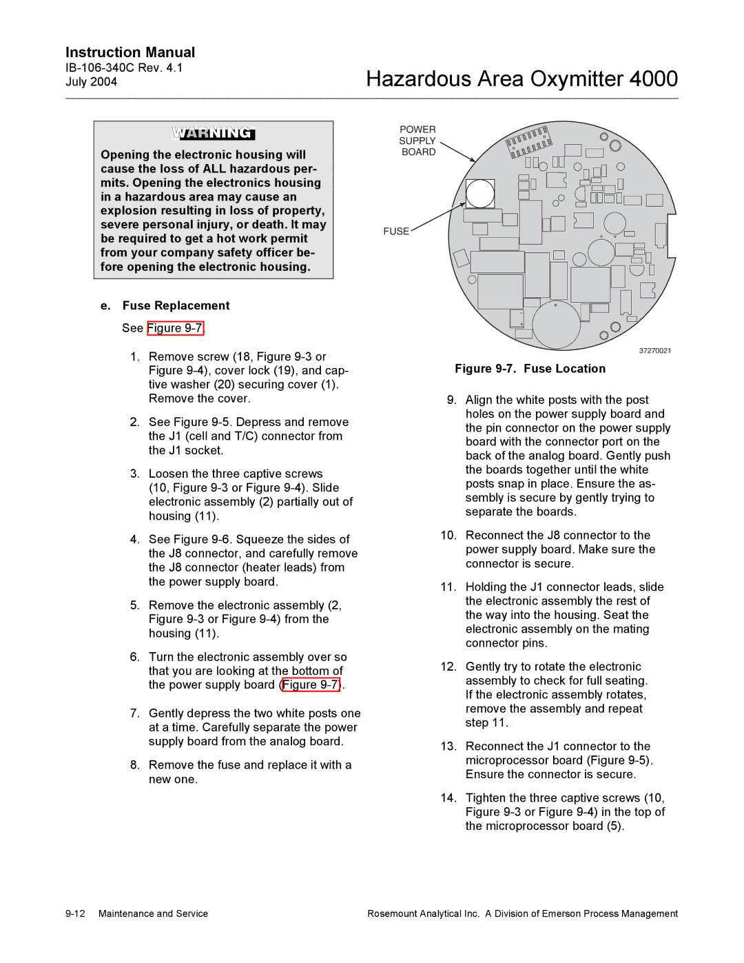
POWER
SUPPLY
BOARD
FUSE
37270021
Figure 9-7. Fuse Location
9.Align the white posts with the post holes on the power supply board and the pin connector on the power supply board with the connector port on the back of the analog board. Gently push the boards together until the white posts snap in place. Ensure the as- sembly is secure by gently trying to separate the boards.
10.Reconnect the J8 connector to the power supply board. Make sure the connector is secure.
11.Holding the J1 connector leads, slide the electronic assembly the rest of the way into the housing. Seat the electronic assembly on the mating connector pins.
12.Gently try to rotate the electronic assembly to check for full seating. If the electronic assembly rotates, remove the assembly and repeat step 11.
13.Reconnect the J1 connector to the microprocessor board (Figure
14.Tighten the three captive screws (10, Figure
Rosemount Analytical Inc. A Division of Emerson Process Management |