Hazardous Area Oxymitter 4000
Instruction Manual
When working on this equipment on the laboratory bench, be aware that the Hazardous Area Oxymitter 4000, probe tube, and flame arrestor hub can be hot [up to 300°C (572°F)] in the region of the probe heater.
h.Cell Replacement
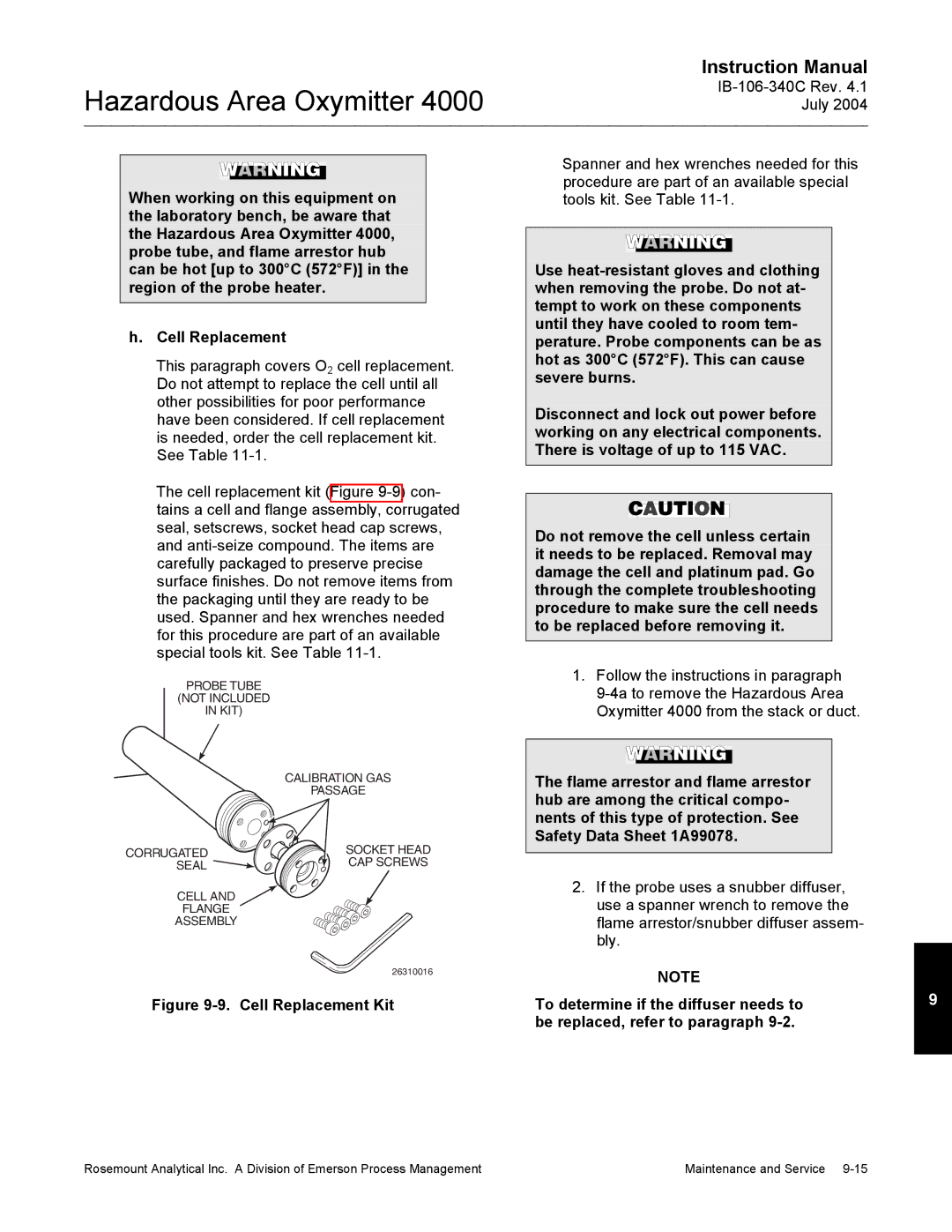
This paragraph covers O2 cell replacement. Do not attempt to replace the cell until all other possibilities for poor performance have been considered. If cell replacement is needed, order the cell replacement kit. See Table
The cell replacement kit (Figure
PROBE TUBE
(NOT INCLUDED
IN KIT)
CALIBRATION GAS
PASSAGE
CORRUGATED | SOCKET HEAD |
SEAL | CAP SCREWS |
CELL AND
FLANGE
ASSEMBLY
26310016
Figure 9-9. Cell Replacement Kit
Spanner and hex wrenches needed for this procedure are part of an available special tools kit. See Table
Use
Disconnect and lock out power before working on any electrical components. There is voltage of up to 115 VAC.
Do not remove the cell unless certain it needs to be replaced. Removal may damage the cell and platinum pad. Go through the complete troubleshooting procedure to make sure the cell needs to be replaced before removing it.
1.Follow the instructions in paragraph
The flame arrestor and flame arrestor hub are among the critical compo- nents of this type of protection. See Safety Data Sheet 1A99078.
2.If the probe uses a snubber diffuser, use a spanner wrench to remove the flame arrestor/snubber diffuser assem- bly.
NOTE |
|
To determine if the diffuser needs to | 9 |
be replaced, refer to paragraph |
|
Rosemount Analytical Inc. A Division of Emerson Process Management | Maintenance and Service |