Instruction Manual
Hazardous Area Oxymitter 4000
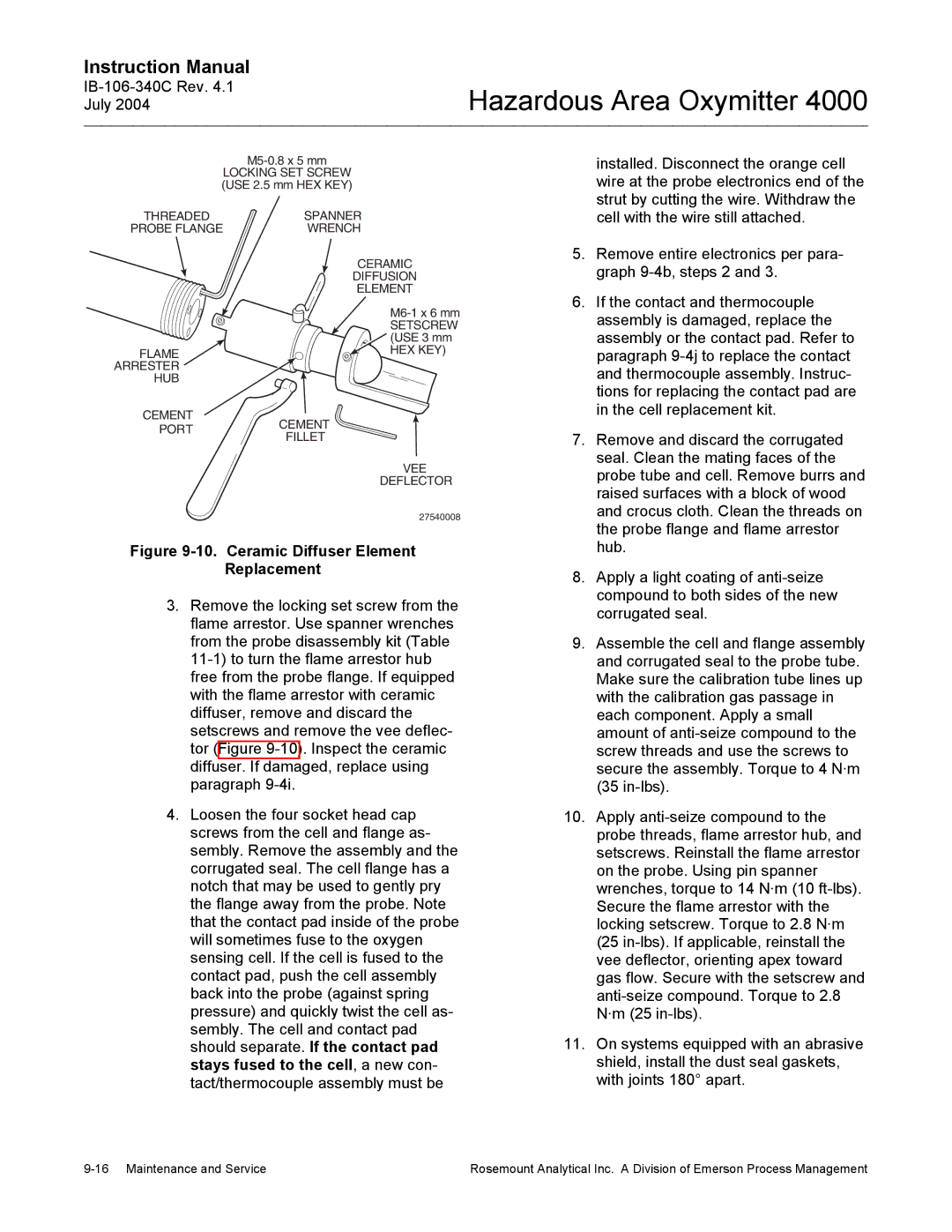
LOCKING SET SCREW (USE 2.5 mm HEX KEY)
THREADED | SPANNER |
PROBE FLANGE | WRENCH |
CERAMIC
DIFFUSION
ELEMENT
installed. Disconnect the orange cell wire at the probe electronics end of the strut by cutting the wire. Withdraw the cell with the wire still attached.
5. | Remove entire electronics per para- |
| graph |
6. | If the contact and thermocouple |
FLAME ARRESTER HUB
SETSCREW (USE 3 mm
HEX KEY)
assembly is damaged, replace the |
assembly or the contact pad. Refer to |
paragraph |
and thermocouple assembly. Instruc- |
tions for replacing the contact pad are |
in the cell replacement kit. |
CEMENT
PORTCEMENT
FILLET
VEE
DEFLECTOR
27540008
Figure 9-10. Ceramic Diffuser Element
Replacement
3.Remove the locking set screw from the flame arrestor. Use spanner wrenches from the probe disassembly kit (Table
4.Loosen the four socket head cap screws from the cell and flange as- sembly. Remove the assembly and the corrugated seal. The cell flange has a notch that may be used to gently pry the flange away from the probe. Note that the contact pad inside of the probe will sometimes fuse to the oxygen sensing cell. If the cell is fused to the contact pad, push the cell assembly back into the probe (against spring pressure) and quickly twist the cell as- sembly. The cell and contact pad should separate. If the contact pad stays fused to the cell, a new con- tact/thermocouple assembly must be
7. | Remove and discard the corrugated |
| seal. Clean the mating faces of the |
| probe tube and cell. Remove burrs and |
| raised surfaces with a block of wood |
| and crocus cloth. Clean the threads on |
| the probe flange and flame arrestor |
| hub. |
8. | Apply a light coating of |
| compound to both sides of the new |
| corrugated seal. |
9. | Assemble the cell and flange assembly |
| and corrugated seal to the probe tube. |
| Make sure the calibration tube lines up |
| with the calibration gas passage in |
| each component. Apply a small |
| amount of |
| screw threads and use the screws to |
| secure the assembly. Torque to 4 N·m |
| (35 |
10. | Apply |
| probe threads, flame arrestor hub, and |
| setscrews. Reinstall the flame arrestor |
| on the probe. Using pin spanner |
| wrenches, torque to 14 N·m (10 |
| Secure the flame arrestor with the |
| locking setscrew. Torque to 2.8 N·m |
| (25 |
| vee deflector, orienting apex toward |
| gas flow. Secure with the setscrew and |
| |
| N·m (25 |
11. | On systems equipped with an abrasive |
| shield, install the dust seal gaskets, |
| with joints 180° apart. |
Rosemount Analytical Inc. A Division of Emerson Process Management |