Oxymitter
Essential Instructions
Summary
Highlights of Changes
Effective April, 2004 Rev
Effective July, 2004 Rev
Effective April, 2004 Rev Summary
Hazardous Area Oxymitter
Table of Contents
Index
List of Illustrations
List of Tables
Definitions
Preface
Hazardous Area Oxymitter
Belangrijk
Vigtigt
Hazardous Area Oxymitter
Tärkeää
Hazardous Area Oxymitter
Wichtig
Importante
Viktig
Hazardous Area Oxymitter
Hazardous Area Oxymitter
Viktigt
Hazardous Area Oxymitter
Section I. Identification
Section II. Physical Data
Section V. Health Hazard Data
Section VI. Reactivity Data
Section VII. Spill or Leak Procedures
Section IX. Special Precautions
Hazardous Area Oxymitter
Hazardous Area Oxymitter
System Overview
Section Description and Specifications
Component Checklist of Typical System Package Contents
Typical System Package
Hazardous Area Oxymitter
System Configuration
Imps
Remote Mounted
Membrane Keypad
System Features
Hazardous Area Oxymitter
Hart
Multiprobe
Standard
Autocalibration
Option
Logic I/O Regulator Calibration
Model 751 Remote Powdered Loop LCD Display
SPS 4000 Optional
Probe Options
Flame Arrestor Ceramic Diffusion Assembly
Abrasive Shield Assembly
View a View B
Specifications
Hazardous Area Oxymitter 4000 with Remote Electronics
Hazardous Area Certifications
Hazardous Area Oxymitter 4000 with Integral Electronics
Code Sensing Probe Type with Flame Arrestor
Product Matrix
Code Language
Part Number Description
Calibration Components
Selecting Location
Section Installation
Mechanical Installation
Hazardous Area Oxymitter 4000 Probe Installation
DIA Millimeters with Inches in Parentheses
Hazardous Area Oxymitter 4000 Probe with Abrasive Shield
Mounting Plate Outline
Probe Mounting
Abrasive Shield Mounting
Orienting the Optional Vee Deflector
Remote Electronics Mounting
Hazardous Area Oxymitter
Integral Electronics Without SPS
All wiring must conform to local and national codes
Wiring Diagram
Probe
Reference Air Package
Pneumatic Installation
SPS 4000 Connections
Imps 4000 Connections
Hazardous Area Oxymitter
General
Verify Mechanical Installation
SW2
Verify Hazardous Area Oxymitter 4000 Configuration
Defaults Hazardous Area Oxymitter 4000 with Membrane Keypad
Calibration Handshake Signal
Alarm
Logic I/O Configuration as set at HART/AMS or LOI Mode
Logic I/O
Calibration
Hazardous Area Oxymitter
Electronics Housing Terminals with LOI
Verify Hazardous Area Oxymitter 4000 Configuration
Defaults Hazardous Area Oxymitter 4000 with LOI
Logic I/O
MA Signal Upon Critical Alarm
Recommended Configuration
Hazardous Area Oxymitter
Error
Power UP
Startup Display
Operating Display
Reference Air
Keypad
Operation
Overview
Normal Operation
Hazardous Area Oxymitter
O2 2.59% LK normal
O2 0.00% LK warm up 367dgC
LOI
Start UP Oxymitter 4000 Calibration
Lockout
LOI Features
Local Operator Interface Menu Tree Sheet 1
LOI Menu Tree
SYSTEM/Calibration Setup
Hazardous Area Oxymitter 4000 Setup AT the LOI
SYSTEM/Parameters
SYSTEM/Input/Output
SYSTEM/Status
LOI Installation
SYSTEM/Software
Sensor Data
LCD Display Optional
Model 751 Remote Powered Loop
Oxymitter 4000 Test Points
Hazardous Area Oxymitter
Section HART/AMS
Hart Communicator Signal Line
Overview
Connections
Signal Line Connections, ≥ 250 Ohms Load Resistance
OFF-LINE and ON-LINE Operations
Hart Communicator PC Connections
Mode Configuration
Logic I/O Configuration as set at HART/AMS or LOI
HART/AMS Menu Tree Sheet 1
HART/AMS Menu Tree Sheet 2
HART/AMS Menu Tree Sheet 3
Complete CAL Recommended Apply GAS GAS 1 Flow
Hart Communicator O2 CAL Method
O2 Calibration
Defining a Timed Calibration VIA Hart
Hazardous Area Oxymitter
EMFmV
Section Troubleshooting
Alarm Indications
Indications
Alarm Contacts
Identifying and Correcting Alarm
LED
Flashes Status MA Line Fault Clearing
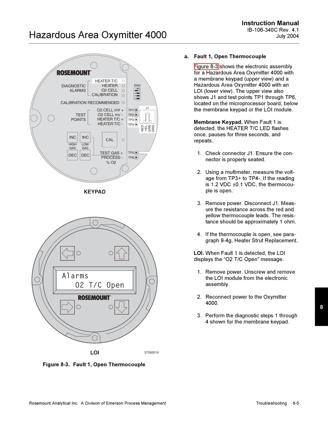
Fault 1, Open Thermocouple
Alarms O2 T/C Open
Membrane Keypad. When Fault 1 is
Keypad
Membrane Keypad. When Fault 2 is
Alarms O2 T/C Shorted
Fault 2, Shorted Thermocouple
Fault 3, Reversed Thermocouple Wiring
Alarms O2 T/C Reversed
Or Faulty PC Board
Membrane Keypad. When Fault 3 is
Fault 4, A/D Comm Error
Alarms ADC Error
Membrane Keypad. When Fault 5 is
Alarms O2 Heater Open
Fault 5, Open Heater
Membrane Keypad. When Fault 6 is
Alarms Very Hi O2 Temp
Fault 6, High High Heater Temp
Membrane Keypad. When Fault 7 is
Alarms Board Temp Hi
Fault 7, High Case Temp
Membrane Keypad. When Fault 8 is
Alarms O2 Temp Low
Fault 8, Low Heater Temp
Membrane Keypad. When Fault 9 is
Alarms O2 Temp Hi
Fault 9, High Heater Temp
Membrane Keypad. When Fault 10 is
Alarms O2 Cell Open
Fault 10, High Cell mV
Membrane Keypad. When Fault 11 is
Alarms O2 Cell Bad
Fault 11, Bad Cell
Membrane Keypad. When Fault 12 is
Fault 12, EEprom Corrupt
Membrane Keypad. When Fault 13 is
Fault 13, Invalid Slope
Membrane Keypad. When Fault 14 is
Fault 14, Invalid Constant
Membrane Keypad. When Fault 15 is
Alarms Calib Failed
Fault 15, Last Calibration Failed
How do I detect a plugged diffuser?
Probe passes calibration, but still ap- pears to read high
Probe passes calibration, but still appears to read low
Can I calibrate a badly plugged diffuser?
Calibration Record For Rosemount Analytical In Situ O2 Probe
Calibration Hazardous Area Oxymitter 4000 with Keypad
Section Maintenance and Service
Installed in a safe area
Hazardous Area Oxymitter
Manual Calibration
Alarms
Oxymitter 4000 with LOI
Calibration Hazardous Area
Abort Calibration
Purgexxxxs
Cal Constants Results of the Calibration
Calibration Status
Hazardous Area Oxymitter 4000 Repair
Integral
Probe Head
Electronic Assembly
Terminal Block Replacement See -3or Figure
J8 Connector
Fuse Location
Hazardous Area Oxymitter
Heater Strut Assembly
Cell Replacement Kit
10. Ceramic Diffuser Element Replacement
Hazardous Area Oxymitter
11. Contact and Thermocouple Assembly Replacement
Contact and Thermocouple Assembly
Section Return of Material
Hazardous Area Oxymitter
Hazardous Area Oxymitter 4000July
Section Replacement Parts
Replacement Parts for Probe Part Number Description Index No
Probe Disassembly Kit
Hazardous Area Oxymitter
Asset Management Solutions AMS
Section Optional Accessories
Hart Handheld 375 Communicator
BY-PASS Packages
SPS 4000 Single Probe Autocalibration Sequencer
Imps 4000 Intelligent Multiprobe Test GAS Sequencer
O2 Calibration GAS
Hazardous Area Oxymitter
Section Index
Hazardous Area Oxymitter
Warranty
Hazardous Area Oxymitter Serial no Order no