Instruction Manual
Hazardous Area Oxymitter 4000
diffusion element into seat. Do not get any cement on upper part of ceramic diffusion element. Ensure complete penetration of cement around 3 grooves in hub. Cement should extrude from opposite hole. Wipe excess material back into holes and wipe top fillet of cement to form a uniform fillet. (A
(j) | Allow filter to dry at room tem- |
| perature overnight or 1 to 2 hours |
| at 93°C (200°F). |
(k) | Wipe a heavy layer of |
| compound onto the threads and |
| mating surfaces of the flame arre- |
| stor, diffusion hub, and probe tube. |
(l) | Assemble flame arrestor and diffu- |
| sion hub with two pin spanner |
| wrenches. Torque to 14 N·m (10 ft- |
| lbs). Secure with hub retaining |
| setscrew. |
(m) On systems equipped with abra- | |
| sive shield, install dust seal gas- |
| kets with joints 180° apart. |
(n) | Reinstall vee deflector, orienting |
| apex toward gas flow. Apply anti- |
| seize compound to setscrews and |
| tighten with hex wrench. |
(o) | Reinstall probe on stack flange. |
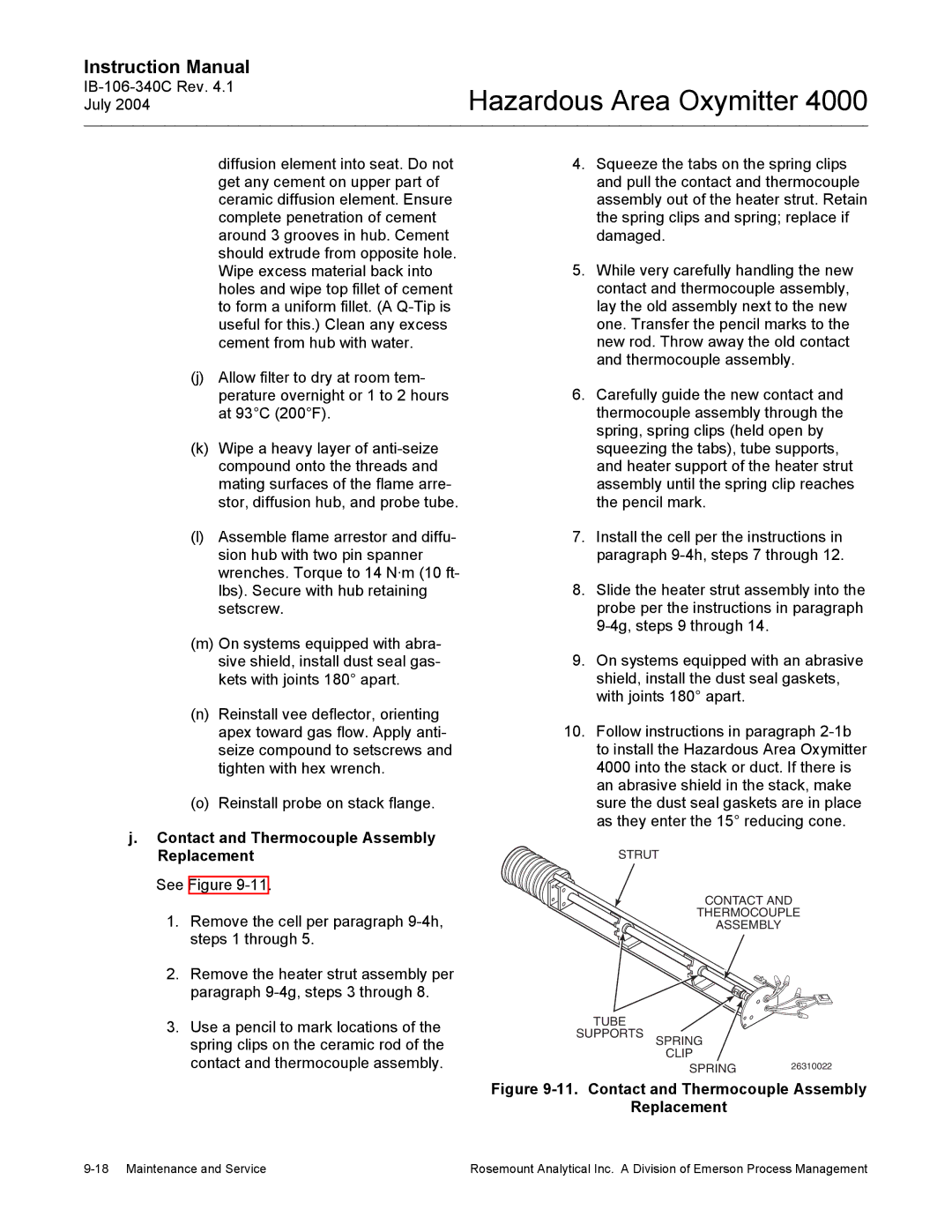
j. Contact and Thermocouple Assembly | |
Replacement | |
See Figure | |
4.Squeeze the tabs on the spring clips and pull the contact and thermocouple assembly out of the heater strut. Retain the spring clips and spring; replace if damaged.
5.While very carefully handling the new contact and thermocouple assembly, lay the old assembly next to the new one. Transfer the pencil marks to the new rod. Throw away the old contact and thermocouple assembly.
6.Carefully guide the new contact and thermocouple assembly through the spring, spring clips (held open by squeezing the tabs), tube supports, and heater support of the heater strut assembly until the spring clip reaches the pencil mark.
7.Install the cell per the instructions in paragraph
8.Slide the heater strut assembly into the probe per the instructions in paragraph
9.On systems equipped with an abrasive shield, install the dust seal gaskets, with joints 180° apart.
10.Follow instructions in paragraph
STRUT
1. | Remove the cell per paragraph |
| steps 1 through 5. |
2. | Remove the heater strut assembly per |
| paragraph |
3. | Use a pencil to mark locations of the |
| spring clips on the ceramic rod of the |
| contact and thermocouple assembly. |
TUBE
SUPPORTS
CONTACT AND
THERMOCOUPLE
ASSEMBLY
SPRING
CLIP
SPRING26310022
Figure 9-11. Contact and Thermocouple Assembly
Replacement
Rosemount Analytical Inc. A Division of Emerson Process Management |