Instruction Manual
Hazardous Area Oxymitter 4000
| d. | When flowing calibration gasses, the raw | work loose. Before troubleshooting the | ||||||||||||||||
|
| cell millivolt value at test points 1 and 2 | system, ensure all ICs are fully seated. | ||||||||||||||||
|
| should represent the levels on the chart in |
|
|
|
|
|
|
|
|
|
|
| ||||||
|
| Figure | d. Electrostatic Discharge | ||||||||||||||||
|
| value increases logarithmically as the O2 | Electrostatic discharge can damage the ICs | ||||||||||||||||
|
| concentration decreases. | |||||||||||||||||
|
| used in the electronics. Before removing or | |||||||||||||||||
|
|
|
|
|
|
|
|
| |||||||||||
|
|
|
|
|
|
|
|
| handling the processor board or the ICs, | ||||||||||
|
|
|
|
|
|
|
|
| |||||||||||
|
|
|
|
|
|
|
|
| ensure you are at ground potential. | ||||||||||
| Install all protective equipment covers |
| |||||||||||||||||
|
|
| |||||||||||||||||
| and safety ground leads after trouble- |
| |||||||||||||||||
| shooting. Failure to install covers and |
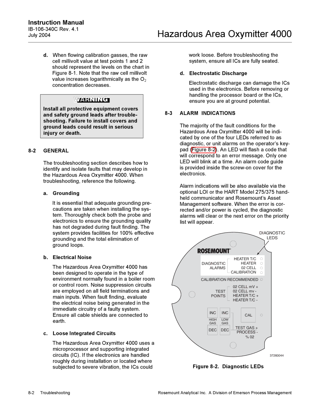
| The majority of the fault conditions for the | ||||||||||||||||
| ground leads could result in serious |
| |||||||||||||||||
| injury or death. |
| Hazardous Area Oxymitter 4000 will be indi- | ||||||||||||||||
|
|
|
|
|
|
|
|
| cated by one of the four LEDs referred to as | ||||||||||
|
|
|
|
|
|
|
|
| |||||||||||
|
|
|
|
|
|
|
|
| diagnostic, or unit alarms on the operator’s key- | ||||||||||
| pad (Figure | ||||||||||||||||||
|
|
|
|
|
|
|
|
| will correspond to an error message. Only one | ||||||||||
| The troubleshooting section describes how to | LED will blink at a time. An alarm code guide | |||||||||||||||||
| identify and isolate faults that may develop in | is provided inside the | |||||||||||||||||
| the Hazardous Area Oxymitter 4000. When | electronics. |
|
|
|
|
|
|
|
| |||||||||
| troubleshooting, reference the following. | Alarm indications will be also available via the | |||||||||||||||||
|
|
|
|
|
|
|
|
| |||||||||||
| a. | Grounding | optional LOI or the HART Model 275/375 hand- | ||||||||||||||||
|
| It is essential that adequate grounding pre- | held communicator and Rosemount’s Asset | ||||||||||||||||
|
| Management software. When the error is cor- | |||||||||||||||||
|
| cautions are taken when installing the sys- | rected and/or power is cycled, the diagnostic | ||||||||||||||||
|
| tem. Thoroughly check both the probe and | alarms will clear or the next error on the priority | ||||||||||||||||
|
| electronics to ensure the grounding quality | list will appear. |
|
|
|
|
|
|
|
| ||||||||
|
| has not degraded during fault finding. The |
|
|
|
|
|
|
|
|
|
|
| ||||||
|
| system provides facilities for 100% effective |
|
|
|
|
|
|
|
|
| DIAGNOSTIC | |||||||
|
| grounding and the total elimination of |
|
|
|
|
|
|
|
|
|
| LEDS | ||||||
|
| ground loops. |
|
|
|
|
|
|
|
|
|
|
| ||||||
| b. | Electrical Noise |
|
|
|
|
|
|
|
|
|
| |||||||
|
|
|
|
|
|
|
| HEATER T/C |
| ||||||||||
|
| The Hazardous Area Oxymitter 4000 has |
| DIAGNOSTIC |
|
| HEATER |
| |||||||||||
|
|
|
| ALARMS |
|
|
| 02 CELL |
| ||||||||||
|
| been designed to operate in the type of |
|
|
|
|
|
| CALIBRATION |
| |||||||||
|
| environment normally found in a boiler room |
| CALIBRATION RECOMMENDED | |||||||||||||||
|
| or control room. Noise suppression circuits |
|
|
|
|
|
| 02 CELL mV + | ||||||||||
|
| are employed on all field terminations and |
|
| TEST |
| 02 CELL mv - | ||||||||||||
|
| main inputs. When fault finding, evaluate |
|
| POINTS |
| HEATER T/C + | ||||||||||||
|
|
|
|
|
|
|
|
|
|
|
| ||||||||
|
| the electrical noise being generated in the |
|
|
|
|
|
| HEATER T/C - | ||||||||||
|
|
|
|
|
|
|
|
|
|
|
|
| |||||||
|
| immediate circuitry of a faulty system. |
|
|
|
|
|
|
|
|
|
|
| ||||||
|
|
|
| INC |
| INC |
|
|
|
|
|
| |||||||
|
| Ensure all cable shields are connected to |
|
|
|
|
|
| CAL |
|
| ||||||||
|
|
|
|
|
|
|
|
|
| ||||||||||
|
|
|
|
|
|
|
|
|
|
| |||||||||
|
| earth. |
|
| GAS |
| GAS |
|
|
|
|
|
| ||||||
|
|
|
|
|
|
|
|
|
|
| HIGH |
| LOW |
|
|
|
|
|
|
|
|
|
|
|
|
|
|
|
|
|
|
|
|
|
| TEST GAS + | |||
| c. | Loose Integrated Circuits |
|
| DEC |
| DEC |
|
| ||||||||||
|
|
|
|
|
|
|
|
|
| ||||||||||
|
|
|
|
|
| PROCESS - | |||||||||||||
|
|
|
|
|
|
|
| ||||||||||||
|
|
|
|
|
|
|
|
|
|
|
|
|
|
|
| ||||
|
|
|
|
|
|
|
|
|
|
|
|
|
| % 02 |
|
| |||
The Hazardous Area Oxymitter 4000 uses a microprocessor and supporting integrated circuits (IC). If the electronics are handled roughly during installation or located where subjected to severe vibration, the ICs could
37260044
Figure 8-2. Diagnostic LEDs
Rosemount Analytical Inc. A Division of Emerson Process Management |