Instruction Manual
Hazardous Area Oxymitter 4000
(f)Restore power to the system; refer to paragraph
NOTE
Recalibration is required whenever electronic cards or sensing cell is replaced.
b.Replacement of Entire Electronics (with Housing) – Hazardous Area Oxymitter 4000 with Integral Electronics.
1.Follow the instructions in paragraph
Do not force the probe housing when installing or removing from the inte- gral electrical barrier/feedthrough (Figure
2. | Remove four screws (22, Figure |
| and washers (21) from the probe tube |
| assembly (23). Remove the probe tube |
| assembly from the housing (11). |
3. | Disconnect the heater and signal wire |
6.Follow the instructions in paragraph
Opening the electronic housing will cause the loss of ALL hazardous per- mits. Opening the electronics housing in hazardous areas may cause an explosion resulting in loss of property, severe personal injury, or death. It may be required to get a hot work permit from your company safety offi- cer before opening the electronic housing.
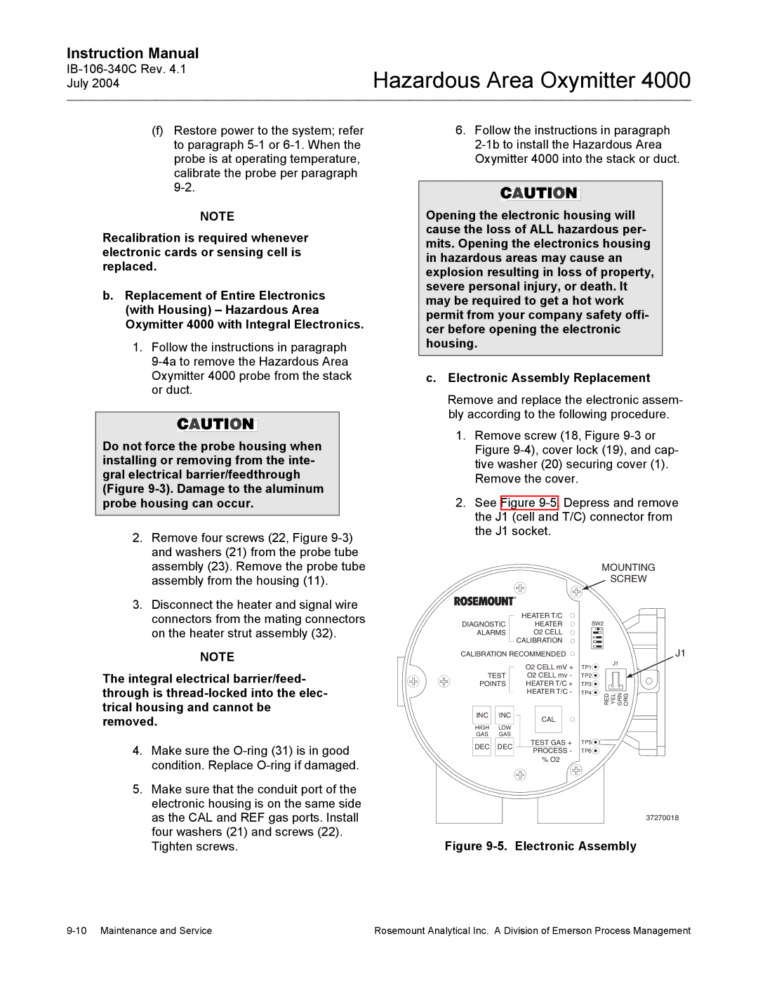
c.Electronic Assembly Replacement
Remove and replace the electronic assem- bly according to the following procedure.
1.Remove screw (18, Figure
2.See Figure
MOUNTING
SCREW
connectors from the mating connectors |
on the heater strut assembly (32). |
NOTE
HEATER T/C
DIAGNOSTIC HEATER
ALARMS O2 CELL CALIBRATION
CALIBRATION RECOMMENDED
SW2
![]() ON
ON
J1
The integral electrical barrier/feed- through is
4. | Make sure the |
| condition. Replace |
5. | Make sure that the conduit port of the |
| electronic housing is on the same side |
| as the CAL and REF gas ports. Install |
| four washers (21) and screws (22). |
TEST
POINTS
INC INC
HIGH LOW
GAS GAS
DEC DEC
O2 CELL mV +
O2 CELL mv - HEATER T/C + HEATER T/C -
CAL
TEST GAS + PROCESS - % O2
TP1 | J1 |
| |
TP2 |
|
TP3 |
|
TP4 | RED YEL GRN ORG |
| |
TP5 |
|
TP6 |
|
37270018
Tighten screws. |
Figure 9-5. Electronic Assembly
Rosemount Analytical Inc. A Division of Emerson Process Management |