Mtpx Plus Series
Safety Instructions English
FCC Class a Notice
Extron Electronics. All rights reserved
Conventions Used in this Guide
Variables are written in slanted form as shown here
Contents
Html Operation
About this Manual
About the Matrix Switchers
Typical Mtpx Plus Twisted Pair Matrix Switcher Application
Mtpx Plus Series Introduction
Transmission distances
TP Cable Advantages
Quality
Video format Sending unit Pre-Peak Maximum distance Off High
Input Output
Mtpx
Maximum distance High quality Variable quality
Video format
Skew equalization
Features
Tie any input to any or all outputs
Mtpx Plus Series Introduction
Rear Panel Cabling and Settings
Mounting the Switcher
Mtpx Plus 3232 Twisted Pair Matrix Switcher
Signal Inputs
TP Cable Termination
Local Inputs VGA connectors Connect analog computer
Input Select switches switchers other than
Captive Screw Connector Wiring for Audio Inputs
RS-232 Output Inserts
RS-232 Output Insert Wiring
Signal Outputs
Captive Screw Connector Wiring for Audio Output
Remote Connection
Mtpx Plus 128 Remote Connector
Cabling
RJ-45 connector wiring
Switcher
Ethernet Connection
Power Connection
Front Panel Configuration Port
Reset Button
Optional 9-pin TRS RS-232 cable
Front Panel, Mtpx Plus
Front Panel Controls and Indicators
Front Panel, Mtpx Plus 816, 168
Input and Output Buttons
Mtpx Plus Series Operation
Control Buttons and LEDs
Mtpx Plus Series Operation
Controls
Button Icons
Front Panel Operations
Front Panel Security Lockouts
Power
Definitions
Creating a Configuration
Confirm the change Press and release the Enter button
Example 1 Create a set of video and audio ties
Clear all selections Press and release the Esc button
Select an input Press and release the input 5 button
Select the output Press and release the Output 1 button
Example 2 Add a video tie to a set of video and audio ties
Example 3 Remove a tie from a set of ties
Example 2, Final Configuration
Select the output Press and release the output 4 button
4 5 6 7 8
Example 3, Final Configuration
Viewing the Configuration
Example
Or background
O Grouping of Incompatible Video Formats
Grouping
Panel see Setting the Front Panel Locks Executive Modes on
Press and release the Input 1 through 4 buttons
Example 5 Grouping inputs and outputs
Select group 1 Press and release the Enter button
Assign inputs and outputs to group
Press and release the Output 5 through 8 buttons
Select group 2 Press and release the Preset button
Press and release the Output 1 through 4 buttons
Press and release the Input 5 through 8 buttons
Preset Locations
Using Presets
Preset Assigned
Example 6 Saving a preset
Example 7 Recalling a preset
Executive Modes on
Muting and Unmuting Audio/RS-232 Outputs
Example 8 Muting and unmuting an audio/RS-232 output
Audio Gain and Attenuation
Viewing and Adjusting the Input Audio Level
Output Button Audio Gain and Attenuation Display
Mtpx Plus 1632, 3216
Mtpx Plus 816, 168
Through show an audio gain level of +8 dB
Example 9 Viewing and adjusting an input audio level
Exit Audio mode Press and release the Audio button
Level Display on an 8-Output-Button Switcher
See Setting the Front Panel Locks Executive Modes on
Viewing and Adjusting the Local Output Volume
Reading the displayed volume
Audio Volume Display
Example 10 Viewing and adjusting a local output volume level
10 11 13 14 15
7 F 10 11
Selecting Lock mode 2 or toggling between mode 2 and mode
Setting the Front Panel Locks Executive Modes
Matrix Software section
Performing a System Reset from the Front Panel
Background Illumination
System Reset
Panel Locks Executive Modes on
Defining the Audio/RS-232 Wire Pair
Serial protocol
Selecting the Rear Panel Remote Port Protocol and Baud Rate
Rear Panel Operations
Performing a Hard Reset Reset
Switcher reverts to the factory default
Reset Mode Comparison/Summary
Soft System Resets
Performing Soft System Resets Resets 3, 4,
Optimizing the Audio
Video Adjustments
Troubleshooting
Worksheet Example 1 System equipment
Configuration Worksheets
Worksheet Example 2 Daily Configuration
Worksheet Example 2 Daily Configuration
Worksheet Example 3 Test Configuration
Worksheet Example 3 Test configuration
Output destinations
Button Switchers Configuration Worksheet
Input sources Output destinations
Programming Guide
Local Host-Control Ports
Configuration port
Found New Hardware Wizard see Installing the Software
Establishing a Connection
Default IP addresses
Connection Timeouts
Ethernet LAN Port
Number of Connections
Host-to-Switcher Instructions
Switcher-initiated Messages
Using Verbose Mode
Exen
Switcher Error Responses
Symbol definitions
Using the Command and Response Tables
X1 =
Read ties
Command and Response Table for SIS Commands
Create Ties
Input signal level/peaking and auto calibrate
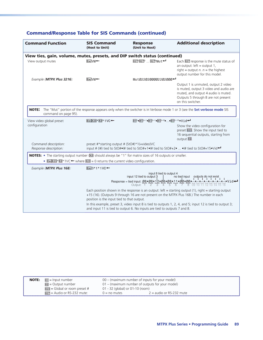
Command/Response Table for SIS Commands
Audio/RS-232 TP input wire pair 3 and 6 configuration
RS-232 output inserts enable
Output pre-peaking
Input skew adjustment
Edid commands
Local video output sync polarity
Output skew adjustment
Audio output volume
Names
Audio or RS-232 mute commands
Audio input gain and attenuation
Grouping
Save, recall, and directly write global presets
Lock executive modes
Outputs 3, 4, 5, and 6 are assigned to room
EZA
Resets
Example Mtpx Plus
Command description Response description
Information requests
Var file = new array List user-supplied files
Mtpx Plus
X6! =
X5! =
X5 =
X6 =
IP setup commands
Command/Response Table for IP-specific SIS Commands
Special Characters
Command/Response Table for IP Setup SIS Commands
Configure the Remote port from the front panel
Matrix Switchers Control Program
Software DVD Window
Installing the Software
Software Operation via Ethernet
Ethernet protocol settings
USB port, the Found New Hardware Wizard appears see see
Using the Matrix Switcher Control Software
Activating a USB port for the first time
Comm Port Selection window appears
Starting and using the program
To run the Matrix Switchers Control Program, click
If the IP address is correct Proceed to b
Address and Password Entry
Sample Program Window Icons Assigned and Ties Created
Control Program IP Setting/Options Window
IP Settings/Options window
Subnet mask
Address and Name fields
Sync Time to PC button
Hardware Address field
Use Dhcp check box
Date, Time local, and GMT offset fields
Typical Mtpx Plus E-mail
Mail Addressee fields
Updating the Firmware
Location of Firmware Upgrade Files
Downloading Firmware Upgrade Files
Select File Window
Ethernet-connected firmware upload
Extron Firmware Loader Window
Serial-port- or USB-port-connected firmware upload
Baud Rate in the Operation section
Firmware Loader Screen
Uploading Html Files
Present on your switcher
File menu
Windows Buttons, Drop Boxes, and Trashcan
Windows menus
Tools menu
Configure Audio Options Window
Mtpx Configuration Settings Window
Edid Configuration window
Status window
Audio Input Configuration selection
Ties Shown as Lines
Preferences menu
Choose Emulate, and click OK
Using Emulation Mode
Master-Reset selection
Using the Help System
Auto calibration
Mtpx Level/Peaking Setting
Optimizing the Video
MTP Transmitter Pre-Peak Selection
Input skew
Mtpx Skew Setting
Manual calibration
Repeat steps 2 through 4 for each receiver to be optimized
MTP Receiver Level/Peaking Setting
Mtpx Plus Pre-Peak Selection
Output skew
Location of Software on the Website
Button-Label Generator Program
Button-Label Generator window appears see figure
Using the Button-Label Generator Software
Html Operation
Download the Startup
Enter Network Password
System Status
Status Tab
Unit Name field
Configuration Tab
System Settings
IP Settings fields
Subnet Mask field
Dhcp radio buttons
IP Address field
Gateway IP Address field
Date/Time Settings Fields
Date/Time Settings fields
Resetting a password
Passwords
Mail IP Address field
Email Settings
Email Address fields
Setting up Smtp authorization
Deselecting Smtp authorization
Domain Name field
Firmware Upgrade
Firmware Upgrade
File Management
File Management Tab
Amber buttons indicate video and audio ties
Control Tab
User Control
Creating a tie
Picture Settings
Changing the skew
MTP signal generator does not work on cable lengths over
Changing the input level/peaking
Toggling output pre-peaking on and off
Mtpx Plus Series Html Operation
Mtpx Configuration
Mtpx Configuration
Changing the input gain and attenuation
Settings
Muting and unmuting an audio or RS-232 output
Changing the output volume level
Number Output Steps Attenuation Volume
Audio volume adjustment settings
Recalling a preset
Global Presets
Saving a preset
Ethernet Link
Default IP Address
Pinging to Determine the Web IP Address
Pinging to Determine the Extron IP Address
Ping with New Address
Computer returns the command prompt C\
Open
Connecting as a Telnet Client
Telnet Tips
Close
Escape character and Esc key
Local echo
Set carriage return-line feed
IP Addresses and Octets
Subnetting a Primer
Gateways
Local and Remote Devices
Masked octets are not compared indicated by X in figure
Determining Whether Devices Are on the Same Subnet
Unmasked octets are compared indicated by ? in figure
Reference Information
Specifications
Video input main see transmitters output specifications
Audio input main see transmitters output specifications
General
Included Parts
Part Numbers and Accessories
Mtpx Plus Matrix Switcher Part Numbers
Replacement Parts and Accessories
Cables
Optional Accessories
UL Rack-Mounting Guidelines
Connectors
Connector
Tabletop Use
Attaching the Mounting Brackets
Mounting Instructions
Button Labels
Installing Labels
Button label blanks, 16-button strips
Europe
USA, Canada, South America Japan Central America
Europe, Africa, and the Middle China East
Asia Middle East