User Guide
Safety Instructions English
Safety Instructions
Trademarks
Copyright
Produit laser de classe
FDA/IEC 60825-1 Requirements
Software Commands
Specifications Availability
Conventions Used in this Guide
Notifications
Page
Contents
117
109
Matrix Software
Html Operation
About this Guide
About the FOX Matrix Switchers
Typical FOX Matrix 3200 Application
FOX Matrix 7200 8U high FOX Matrix 3200 4U high
Features
Fiber Cable Transmission Modes
Tie any input to any or all outputs
Redundant Power Supply Backs up Primary
FOX Matrix 3200 and 7200 Switchers Introduction
Configure the Matrix Switcher
Setup and Installation Checklist
Perform Physical Installation
Get Ready
FOX Matrix 3200 Fiber Optic Matrix Switcher Rear Panel
Rear Panel Boards, Cabling, and Features
Primary Power Supply
Slot
Boards
Connections
Fiber optic boards
3G/HD/SD-SDI boards
Fiber optic I/O board LED indications
Output LED Input LED Definition
Indication Definition
Remote Port
Ethernet Connection
Cabling
RJ-45 connector wiring
Reset Button and LED
Simple FOX Matrix Switcher External Sync Connection Example
Switch Reference Connections
Cooling Fan assemblies
Power Supply Modules and Indicator LEDs
Optional 9-pin TRS RS-232 Cable
Front Panel Configuration Port
Operation
Front Panel Controls and Indicators
Front Panel, FOX Matrix 7200 Switcher
Through
Input and Output Buttons
FOX Matrix 3200 and 7200 Switchers Operation
Lock
Control Buttons
Primary and Redundant Power Supply LEDs
Power Indicators
Button Icons
Rear Panel Power Indicators
Definitions
Front Panel Operations
Creating a Configuration
Power
Example 1 Create a set of ties
3 4 5 6 7 8 15 17 18 19 20 21 22 23 24 31
Example 2 Add a tie to a set of ties
Final Configuration, Example
Example 3 Remove a tie from a set of ties
Select the output Press and release the output 4 button
Example 4 Viewing ties
Viewing the Configuration
4 5 6 7 8 15 18 19 20 21 22 23 24 31
O Grouping of Incompatible Video Formats
Grouping
Press the Preset button to select group
Press the Enter button to select group
Press the View button to select group
Assign inputs and outputs to group
Example 5 Grouping inputs and outputs
Select group 2 Press and release the Preset button
Example 6 Saving a preset
Using Presets
Example 7 Recalling a preset
Example 8 Muting and unmuting an output
Muting and Unmuting Outputs
Mute outputs one at a time
Performing a System Reset from the Front Panel
Locking the Front Panel Executive Mode
Selecting the Rear Panel Remote Port Protocol and Baud Rate
Background Illumination
Reset Operations
See the Matrix Software
Soft System Resets
Performing Soft System Resets Resets 3, 4,
Performing a Hard Reset Reset
Troubleshooting
Worksheet Example 1 System equipment
Configuration Worksheets
Worksheet Example 2 Daily Configuration
Worksheet Example 2 Daily Configuration
Worksheet Example 3 Test Configuration
Worksheet Example 3 Test configuration
Blank Configuration worksheet, FOX Matrix
Output destinations
Programming Guide
Serial Ports
Ethernet LAN Port
Default IP addresses
Establishing a Connection
IP address Subnet mask 255.255.0.0 Gateway address
Connection Timeouts
Host-to-Switcher Instructions
Using Verbose Mode
Number of Connections
Switcher-initiated Messages
Using the Command and Response Tables
Switcher Error Responses
Symbol Definitions
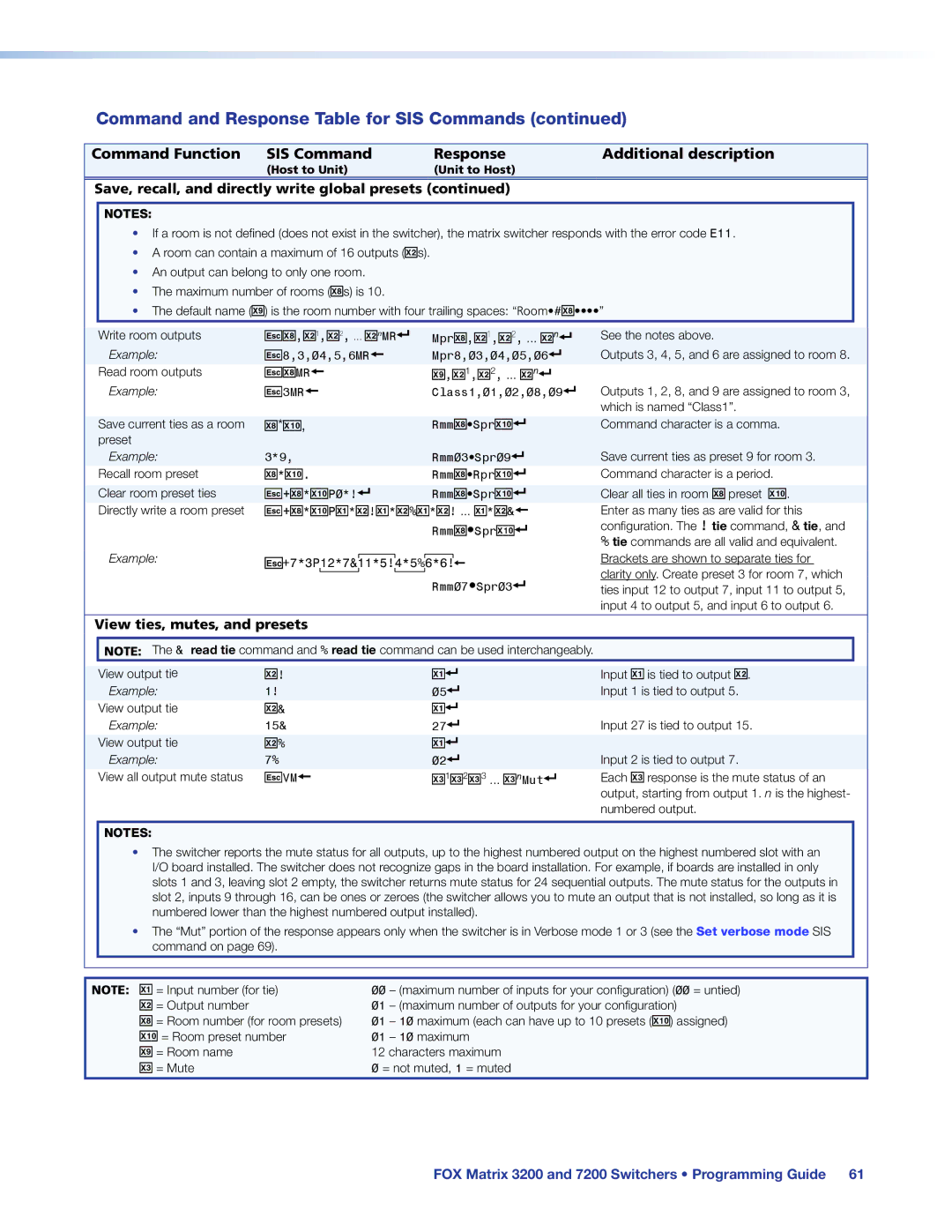
Command and Response Table for SIS Commands
Channel mute commands
Command and Response Table for SIS Commands
Create ties
Read ties
Direct write process
Save, recall, and directly write global presets
Reclocking
Laser controls
EVM
View ties, mutes, and presets
Example 32 x 32 matrix LS
List input link detection
Names
Grouping
Front panel lockout Executive mode
Resets
File management
Information requests
Example Matrix
X5 =
X6$ =
Port mapping
Unit contact name and location
Community names
Special Characters
Access enable
Trap targets
Trap target notifications
Matrix Switchers Control Program
Ethernet protocol settings
Software Operation via Ethernet
Software Operation via a Serial Port
Installing the Software
Comm Port Selection Window
Using the Matrix Switcher Control Software
If the IP address is correct Proceed to b
Address and Password Entry
Sample Program Window Icons Assigned and Ties Created
Address and Name fields
IP Settings/Options window
Hardware Address field
Use Dhcp check box
Date, Time local, and GMT offset fields
Administrator Password and User Password fields
Sync Time to PC button
Use Daylight Saving check box
Mail Server IP Address field
Mail Server Domain Name field
Mail Addressee fields
Updating the Firmware
Downloading Firmware Upgrade Files
Ethernet-connected firmware upload
Extron Firmware Loader Window
Serial-port-connected firmware upload
Html Files List Window
Uploading Html Files
Windows Buttons, Drop Boxes, and Trash Can
Windows menus
File menu
Status Window
Tools menu
Physical Configuration Window
Ties Shown as Lines
Preferences menu
Master-Reset selection
Using Emulation Mode
Emulate Mode Configuration
Using the Help System
Button Label Generator Program
Installing the Button Label Generator Software
Extron Button Label Generator Window
Using the Button Label Generator Software
Html Operation
Windows Security Dialog Box
Opening the Embedded Web Pages
System Status
Status Tab
Input Link
Input Link
System Settings
Configuration Tab
IP Settings fields
Unit Name field
IP Address field
Dhcp radio buttons
Gateway IP Address field
Subnet Mask field
Date/Time Settings Fields
Date/Time Settings fields
Resetting a password
Passwords
Email Settings
Mail IP Address field
Domain Name field
Setting up Smtp authorization
Deselecting Smtp authorization
Email Address fields
Snmp Settings
Snmp Settings
Snmp Manager Trap Target fields
Snmp General Settings fields
Firmware Upgrade
Firmware Upgrade
File Management
File Management Tab
Set and View Ties
Control Tab
Creating or deleting a tie
Mounting the Switcher
UL Guidelines
FOX Matrix 3200 4U high FOX Matrix 7200 8U high
Battery and Power Precautions
Removing and Installing the I/O Board or Blank Panel
Mounting Instructions
FOX Matrix 7200 only
Removing the I/O Board or Blank Panel
Installing the I/O board or blank panel
Removing and Installing the Power Supply Module
Removing the Power Supply Module
Installing the Power Supply Module
Removing and Installing a Fan Module
Installing a Fan Module
Removing a Fan Module
Installing Labels in the Buttons
Removing and Installing Button Labels
Button Label Blanks
Ethernet Link
Default IP Address
Pinging to Determine the Web IP Address
Pinging to Determine the Extron IP Address
Configuring the Switcher for Network Use via the ARP Command
Connecting as a Telnet Client
Telnet Tips
Open
Local echo
Escape character and Esc key
Set carriage return-line feed
Close
Gateways
Subnetting a Primer
Local and Remote Devices
IP Addresses and Octets
Determining Whether Devices Are on the Same Subnet
Unmasked octets are compared indicated by ? in figure
Masked octets are not compared indicated by X in figure
Extron Warranty