Gemini User’s Manual
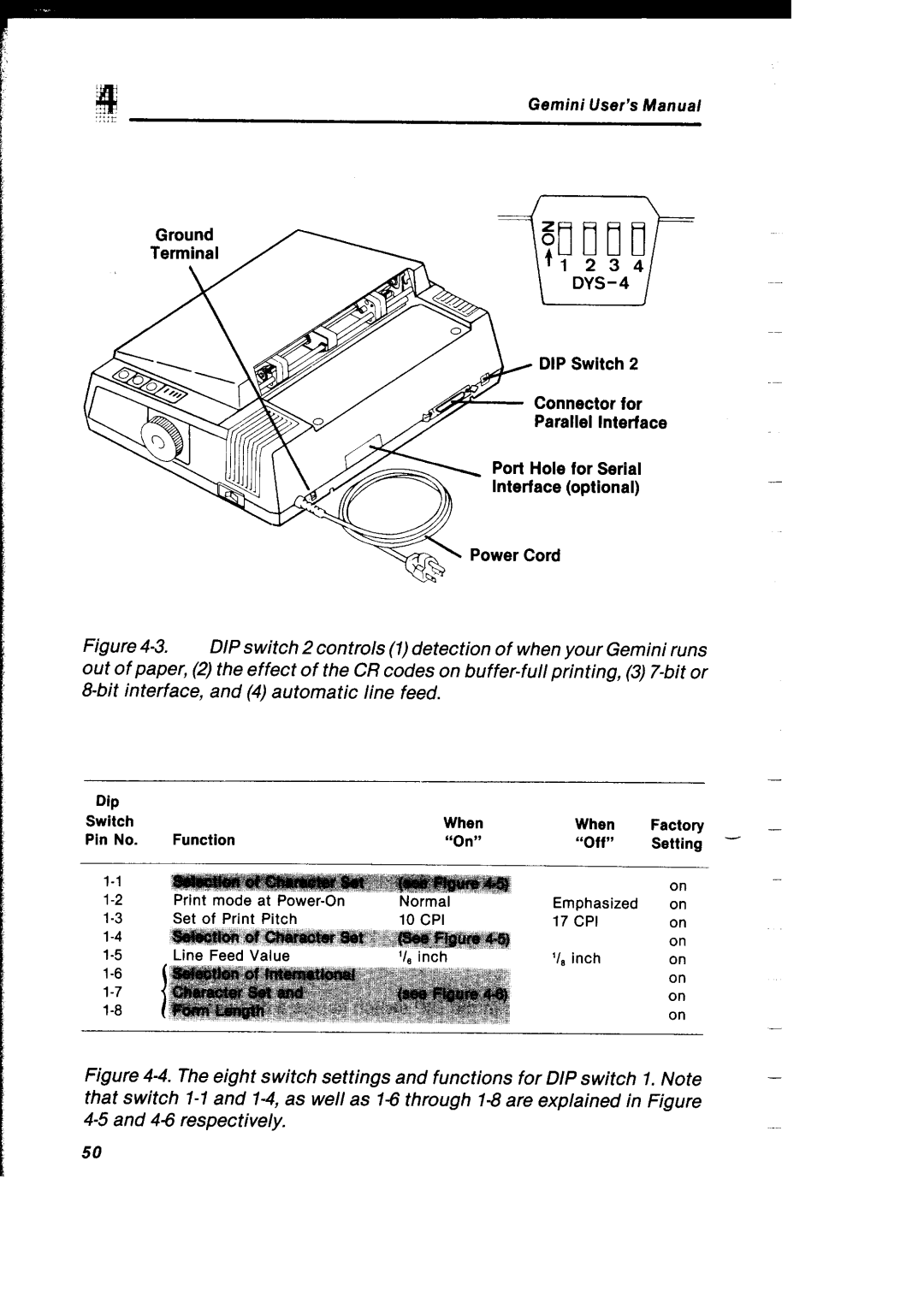
Ground
Terminal
\
DIP Switch 2
Connector for
Parallel Interface
Port Hole for Serial
Interface (optional)
F | Power Cord |
Figure 4-3. DIP switch 2 controls (1)detection of when your Gemini runs out of paper, (2) the effect of the CR codes on buffer-full printing, (3) 7-bit or 8-bit interface, and (4) automatic line feed.
|
|
|
|
| - |
Dip |
|
|
|
|
|
Switch |
| When | When | Factory |
|
Pin No. | Function | “On” | “Off” | Setting - | - |
| on | - | |
|
| ||
Emphasized | on |
| |
17 CPI | on |
| |
| on |
| |
‘I, inch | on |
| |
| on |
| |
| on |
| |
| on | - | |
|
|
| |
Figure | switch settings and functions for DIP switch | 1. Note | - |
that switch |
|
| |
43 and |
|
| |
50
