DCP552 Mark ΙΙ Digital Control Programmer User’s Manual
EN1I-6187 Issue 5 12/01
Warranty
Unpacking
Configuration of This User’s Manual
Contents
Event Output Open Collector Output Connection
Mode transitions
PID group selection
Program Setup
Parameter Setup
Operation
Memory Card Operations
Troubleshooting
Index
Specifications
Calibration
Program Work Sheet Parameter Work Sheet
FUNC+PROG key
Handling Precautions
Conventions Used in This Manual
Disp key, ↑ key
Features
RUN Hold Reset
Basic Function Block Diagram
Total of 49 patterns
Data Configuration Overview
Parameters
CPL communications network-based configuration
System Configuration
Model number DCP552E2
Model Number
Structure
Names and Functions of Parts
Basic display status
Console
Display
MAN
Enter key Enter key
Key pad
# $%
Func + →
Key chord functions
Display channel select key
Loader jack
↑ + Prog
Thermocouple
Resistance temperature detector
Input Type and Range Number
Input
DC current, DC voltage
Mounting position
Before Installation
Dust proof cover
Sources of electrical interference and countermeasures
Panel cutout dimension
Installation
Handling Precautions
Installation procedures
Precautions on Wiring
Wiring
Wiring
Recommended Cables
Making Terminal Connections
11 do
Terminal Array
Model No
Power Supply and Grounding
Power supply
Grounding
PV input CH1 connection
PV Input Analog Input Connection
PV input CH2 connection
Handling Precautions
Open
Control Output Connection
Auxiliary output CH1 connection
Auxiliary Output Connection
EV1 EV2 EV3 EV4 EV5 EV6 EV7 EV8
Event Output Open Collector Output Connection
External Switch Input Connection
RS-485 connection
Communication Connection
RDA RDB SDA SDB
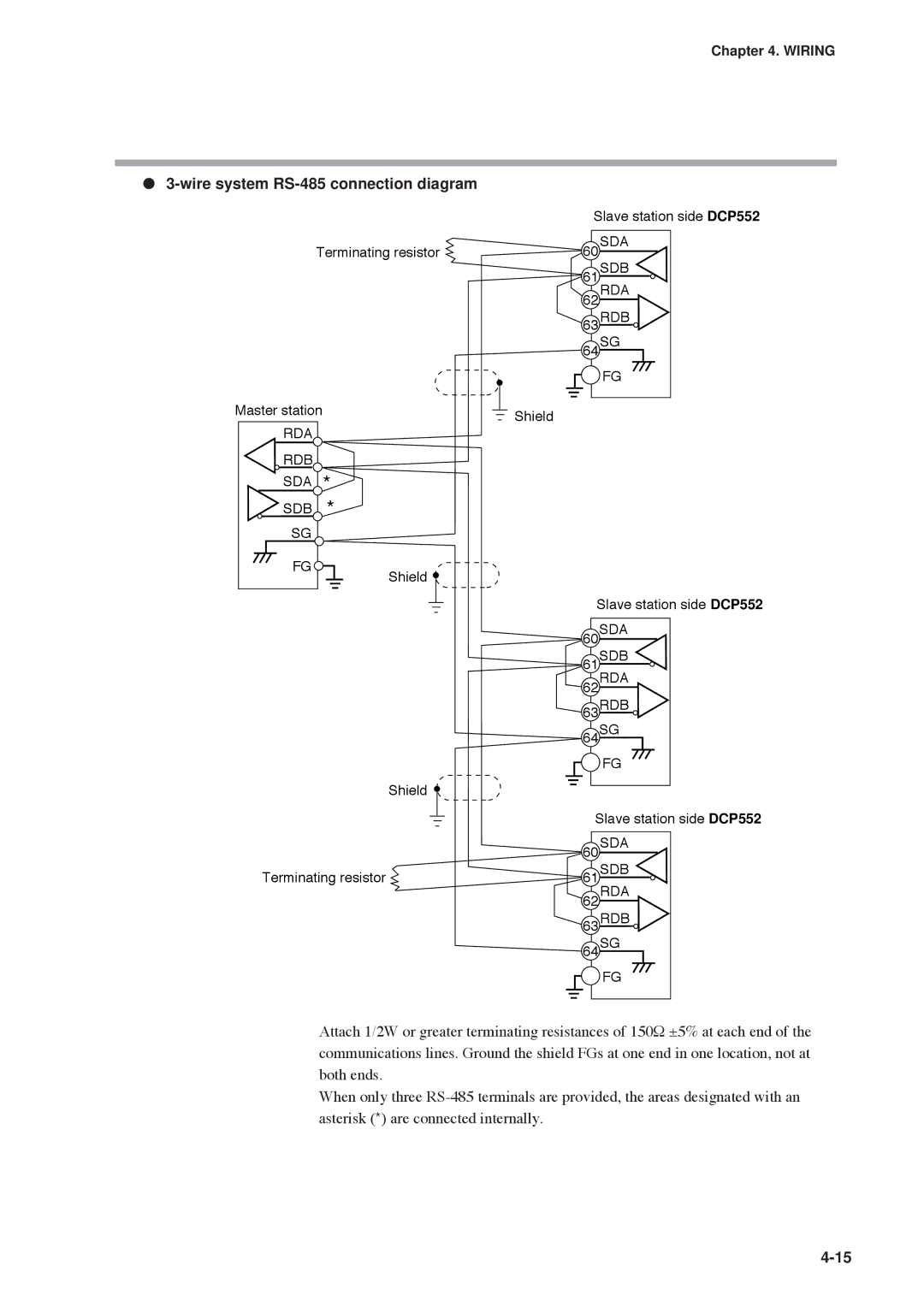
Wire system RS-485 connection diagram
Terminating resistor Master station
RS-232C connection
Connection to ST221
Isolation Between Input and Output
Data types
Data
Pattern
Program Pattern
RAMP-X system
RAMP-E system ∆ SP setting
RAMP-T system θ setting
Xxxxx XXXX.X XXX.XX XX.XXX
Time events
Events
Off-time Output-ON
Output-ON Output-OFF Time
PV event
Basic specifications
Event on delay
SP upper limit SP lower limit MV upper limit MV lower limit
PV deviation rate event
Code event
Example Setting a timed code with 3 output points in event
Functions
Basic operations
Mode event
Selection of ouput limiter group
PID group selection
Soak at start of segment
Soak Guarantee soak
Soak at end of segment
PV shift
Repeat
PV start
Cycle
Pattern link
Tag
Constant value control
Mode types
Mode
Program operation
Hold
Indicated by the dashed lines in the figure below
Mode transitions
Operation end
Mode transition operations
RUN Hold Reset ADV Fast
Mode transition restrictions
Model without carbon potential CP compensation
Input Process Functions
PV1
Model with carbon potential CP compensation
Operation
Setting
O2 sensor check model with CP compensation
Objective
Output Processing Functions
Current output with setup data C21 set to
Control output CH1
PID parameter oL, oH are valid when setup
Control output CH2
5G output with setup data C22 set to
AT not performed during CH2 O2 sensor input
Auxiliary output
Auxiliary output
Startup flow procedure
Power Supply On
Basic Display Selection
##!#
Disp key function When variable parametar PA03 is set to
Program run mode displays
Display A1 Display A2 Display A3
Display A5
Display A4
Display A6
Display B1 Display B2 Display B3
Disp key function when variable parameter PA03 is set to
Display B5 Display B6
Display B4
Handling Precautions
Display D5 Display D6
Message key function when variable parameter PA03 is set to
Display D1
Display D2 Display D3 Display D4
Display E1 Display E2 Display E3
Constant value control mode
Display F4
Display F1 Display F2 Display F3
Selecting program numbers
Selecting Programs
External switch input
External Switch Operation
Types of external switch inputs
BCD system
Selecting programs
Binary system
###
SW1 to 8 and 15 to 16 timing
Read timing
SW9 to 14 and RUN, Fast Ready Fast timing
Auto-tuning AT
Manual Operation and Auto-Tuning
Manual operation
TP-A7 TP-A6 TP-A5 TP-A4 TP-A3 TP-A2 TP-A1
ConSt when using Func + PID key
Parameter Setup
Selecting parameter settings groups
Progression of individual items in parameter settings
Modifying individual items and exiting the setting mode
↑ ↓
Parameter Setting List
$$$$$
Variable parameter setting
=C627
C30*#*6727
C22
Detailed information on variable parameters
OFF
PA05 program autoload
PA17
PA31 to PA38 event on delay groups 1 to 4, event/delay time
$$$$
Settings by event type
++++,%
679
%97
32 #
1rE
PID parameter CH1 setting
CP-A1
CP-A5
#CP %
PID parameter CH2 setting
OL-6 OH-6 1d-7 RE-7 OL-7 OH-7
CP-A6
C01016
Setup data setting
C11##
0000
=111111
?97
367
C100
Detailed descriptions of setup data settings
Remaining segment time Total operation time
C63 time display
SSR = I 0 ⋅ Z + V D
C95 voltage output control C96 voltage output control
Equation
C100 PV2 zener barrier adjustment
Handing Precautions
Constant value control data CH2 setting
Constant value control data CH1 setting
Selecting number of program to operate
Program Setup
Selecting channel of program to operate
Start of display items
Starting programming
State transition
Key operations
Program Setup
Programming map
5555555555
Display items
Setting pattern items
Display
When the event is a PV event
Setting event items Handling Precautions
Display PV events
Display time event
When the event is a time event
Display code event
When the event is a code event
Display Code event with a timer function
When the event is a timer code event
When the event is an instrument event
When the event is an event off
Setting PID groups and output limiter group number items
Setting G.SOAK Guarantee soak items
Setting PV shift items
Setting repeat items
Setting PV start items
Setting cycle items
Setting pattern link items
↓key ↑key
Setting tag items
Deleting programs
Display segment insertion Display segment deletion
Inserting and deleting segments
Program Setup
Copying Programs
Program copy procedures
General reset procedures
General Reset
Memory card types
Memory Card Type and Functions
Memory card functions
Save menu
Save Procedures
Procedures for saving single programs
Procedures for formatting cards
Procedures for saving setup data
Procedures for saving all programs
Procedures for saving variable parameters
Procedures for saving event configuration data
Procedures for saving PID parameters
Procedures for saving all parameters
Load menu
Load Procedures
Procedures for loading individual programs
Card battery alarm panel
Procedures for loading PID parameters
Procedures for loading all programs
Procedures for loading setup data
Procedures for loading variable parameters
DCP552 Mark
Procedures for loading event configuration data
Procedures for loading all parameters
DCP552
Operation and action
Key operated autoload procedure
Autoload
Conditions
Auto load using external switch inputs
Error Message List
Power on self-diagnostic routines
10 1 Self-Diagnostic Functions and Alarm Code Displays
Self-diagnostic routines performed each sampling cycle
Alarm classification
Alarm code display
10-2
Normal display mode problems
10 2 Key Input Related Problems
Autotuning AT cannot be started with AT key
Fast mode cannot be invoked with Func and → keys
Manual mode cannot be invoked with A/M key
Auto mode cannot be invoked with A/M key
10-5
Autotuning cannot be canceled with AT key
Setup data setting state cannot be invoked with Setup key
Program copy cannot be performed with ↑ and Prog keys
Event items cannot be displayed with ↑ and ↓ keys
Parameter setting related problems
Program setting related problems
Registration state cannot be invoked with Enter key
10-7
C60
Items to be provided by the user
10 3 When the BAT LED Flashes
Replacing the battery
BAT LED flashes
10-9
Battery replacement procedures
10-10
Troubleshooting
10-11
11-1
53!7
11-2
342
11-3
11-4
11-5
$0+A
11-6
?A!2
11-7
Attachment/auxiliary devices list
DCP552
11 2 External Dimensions
11-8
Equipment needed
Precautions before calibration
12-1
12-2
12 1 Quick Reference Table for Calibration Items
12-3
$! AdJS?
12-4
12-5
Calibration Flowchart 2/3
12-6
Calibration Flowchart 3/3
Enter calibration mode
12 2 Calibration Procedures
12-7
Key Key test
Function test
12-8
Digital input test
Display test
12-9
Digital output test for event
Digital output test for control output
12-10
Gain No. select
Built-in clock adjustment
PV calibration
Input CH No. select
Writing into Eeprom
PV zero, span
Press Enter key 12-12
12-13
Cold junction sensor calibration
Current output calibration
Key Carbon potential code calibration
Carbon potential code calibration
12-16
12-17
Set Up
11. Current Outputs
12-18
Pattern graph
DCP552 Parameter Work Sheet
Variable parameter setting
Denotes items settable only on models with CP compensation
PA100
PA111
DCP552 Parameter Work Sheet Event configuration data setting
E12-1
Event type
RUN, HOLD, END, Fast
145 to
OL-1
DCP552 Parameter Work Sheet PID parameter CH1 setting
CP-A3
CP-A4
DCP552 Parameter Work Sheet PID parameter CH2 setting
CP-A1
CP-A4
6D output Voltage time proportional control output system B
DCP552 Parameter Work Sheet Setup data setting
19999 to +20000 SPU C45 not equal to
RAMP-E
C100
ConSt
Fixed command control data CH2 setting
Page
Page
Page
Page
Page
Page
Page
Page
Page
Page
Page
Page
Index-1
Index
Index-2
PV start
00-11 4th Edition
Revision History
97-12 EN1I-6187 1st Edition 98-05 2nd Edition
98-11 3rd Edition
01-12 EN1I-6187 5th Edition
Honeywell Service Centers
Argentina
No. CP-UM-5025E