Input #2
Thermocouple | RTD | Millivolt or Volts | |
except | |||
|
|
Use Thermocouple extension wire only
22 R
3![]()
![]() 23 +
23 +
24 –
![]() 22 R
22 R
![]()
![]() 23 +
23 + ![]() 24 –
24 –
![]()
![]() 22 R
22 R
mV or | + | 23 + |
Volt |
|
|
source | – | 24 – |
| Milliamps | Thermocouple Differential |
+
1
–
100K 1
2
100K 3
![]() 22 R
22 R
![]() 23 +
23 + ![]() 24 –
24 –
–![]() 22 R
22 R
Xmitter |
| 1 |
|
+ |
| 23 + | |
250 | Ω | ||
|
|
| |
Power |
| 24 – | |
+ | – | ||
Supply |
|
| |
Use Thermocouple |
|
| ||
extension wire only | 22 | R | ||
+ |
| |||
|
|
| ||
– |
| 23 + | ||
2 |
|
| ||
– | 24 | – | ||
| ||||
+ |
|
|
| |
Slidewire Input
(for Position Proportional Control or Three Position Step Control)
| 4 |
|
Open | 22 | R |
Wiper | 23 | + |
Close | 24 | – |
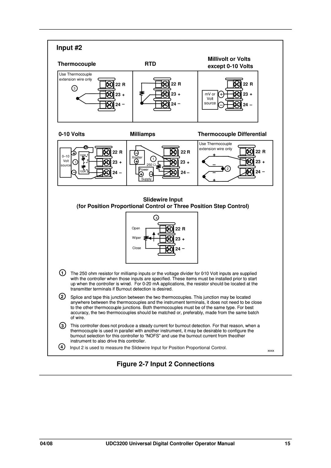
1The 250 ohm resistor for milliamp inputs or the voltage divider for
2Splice and tape this junction between the two thermocouples. This junction may be located anywhere between the thermocouples and the instrument terminals, it does not need to be close to the other thermocouple junctions. Both thermocouples must be of the same type. For best accuracy, the two thermocouples should be matched or, preferably, made from the same batch of wire.
3This controller does not produce a steady current for burnout detection. For that reason, when a thermocouple is used in parallel with another instrument, it may be desirable to configure the burnout selection for this controller to “NOFS” and use the burnout current from theother instrument to also drive this controller.
4 Input 2 is used to measure the Slidewire Input for Position Proportional Control. | xxxx |
|
Figure 2-7 Input 2 Connections
04/08 | UDC3200 Universal Digital Controller Operator Manual | 15 |
