1 Introduction
1.1 Operator Interface
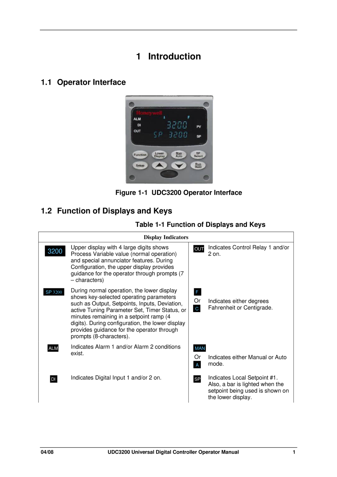
Figure 1-1 UDC3200 Operator Interface
1.2 Function of Displays and Keys
Table 1-1 Function of Displays and Keys
Display Indicators
3200 |
SP 3200
ALM
DI
Upper display with 4 large digits shows Process Variable value (normal operation) and special annunciator features. During Configuration, the upper display provides guidance for the operator through prompts (7
– characters)
During normal operation, the lower display shows
Indicates Alarm 1 and/or Alarm 2 conditions exist.
Indicates Digital Input 1 and/or 2 on.
OUT Indicates Control Relay 1 and/or 2 on.
F
Or Indicates either degrees
CFahrenheit or Centigrade.
MAN
Or Indicates either Manual or Auto
Amode.
SP Indicates Local Setpoint #1. Also, a bar is lighted when the setpoint being used is shown on the lower display.
04/08 | UDC3200 Universal Digital Controller Operator Manual | 1 |