Function | Selections or |
Prompt | Range of Setting |
Lower Display | Upper Display |
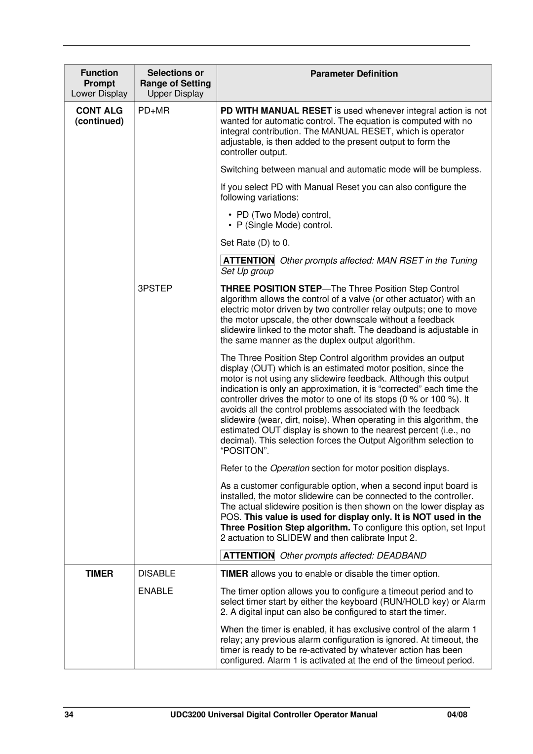
CONT ALG | PD+MR |
(continued) |
|
3PSTEP
TIMER | DISABLE |
| ENABLE |
Parameter Definition
PD WITH MANUAL RESET is used whenever integral action is not wanted for automatic control. The equation is computed with no integral contribution. The MANUAL RESET, which is operator adjustable, is then added to the present output to form the controller output.
Switching between manual and automatic mode will be bumpless.
If you select PD with Manual Reset you can also configure the following variations:
•PD (Two Mode) control,
•P (Single Mode) control.
Set Rate (D) to 0.
ATTENTION Other prompts affected: MAN RSET in the Tuning Set Up group
THREE POSITION
The Three Position Step Control algorithm provides an output display (OUT) which is an estimated motor position, since the motor is not using any slidewire feedback. Although this output indication is only an approximation, it is “corrected” each time the controller drives the motor to one of its stops (0 % or 100 %). It avoids all the control problems associated with the feedback slidewire (wear, dirt, noise). When operating in this algorithm, the estimated OUT display is shown to the nearest percent (i.e., no decimal). This selection forces the Output Algorithm selection to “POSITON”.
Refer to the Operation section for motor position displays.
As a customer configurable option, when a second input board is installed, the motor slidewire can be connected to the controller. The actual slidewire position is then shown on the lower display as POS. This value is used for display only. It is NOT used in the Three Position Step algorithm. To configure this option, set Input 2 actuation to SLIDEW and then calibrate Input 2.
ATTENTION Other prompts affected: DEADBAND
TIMER allows you to enable or disable the timer option.
The timer option allows you to configure a timeout period and to select timer start by either the keyboard (RUN/HOLD key) or Alarm 2. A digital input can also be configured to start the timer.
When the timer is enabled, it has exclusive control of the alarm 1 relay; any previous alarm configuration is ignored. At timeout, the timer is ready to be
34 | UDC3200 Universal Digital Controller Operator Manual | 04/08 |
