3.11 Options Group
| Function | Selections or | |
| Prompt | Range of Setting | |
| Lower Display | Upper Display | |
| AUX OUT |
| |
|
|
|
|
| ATTENTION |
| |
| Prompts for the |
| |
| Auxiliary |
| |
| Output |
| |
| Selection |
| |
| appear only if |
| |
| one of the |
| |
| Auxiliary |
| |
| Output boards |
| |
| is installed. |
| |
|
|
| DISABLE |
|
|
| INPUT 1 |
|
|
| INPUT 2 |
|
|
| PV |
|
|
| |
|
|
|
|
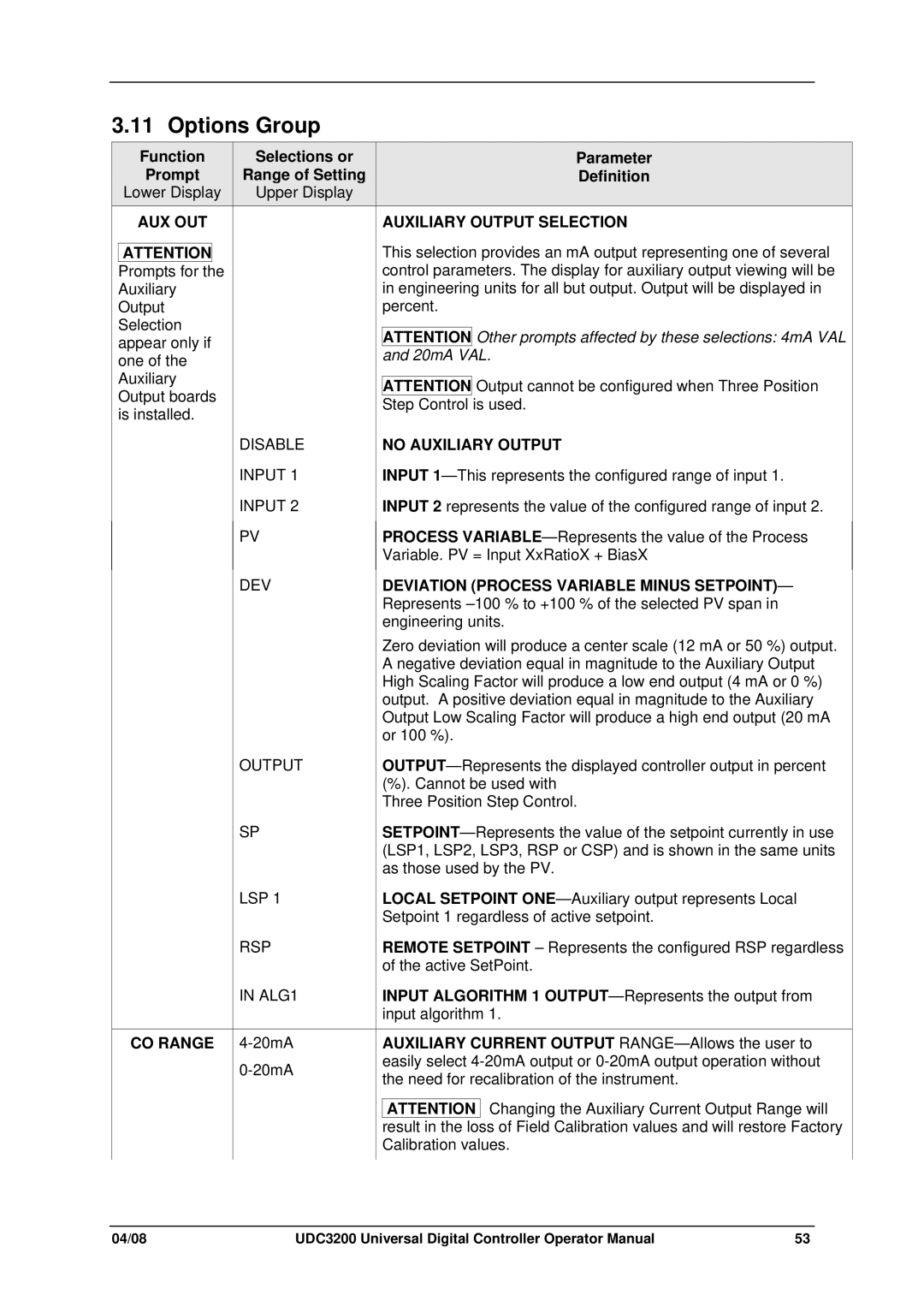
Parameter
Definition
AUXILIARY OUTPUT SELECTION
This selection provides an mA output representing one of several control parameters. The display for auxiliary output viewing will be in engineering units for all but output. Output will be displayed in percent.
ATTENTION Other prompts affected by these selections: 4mA VAL and 20mA VAL.
ATTENTION Output cannot be configured when Three Position Step Control is used.
NO AUXILIARY OUTPUT
INPUT
INPUT 2 represents the value of the configured range of input 2.
PROCESS
DEV
OUTPUT
SP
LSP 1
RSP
IN ALG1
CO RANGE 4-20mA
DEVIATION (PROCESS VARIABLE MINUS SETPOINT)— Represents
Zero deviation will produce a center scale (12 mA or 50 %) output. A negative deviation equal in magnitude to the Auxiliary Output High Scaling Factor will produce a low end output (4 mA or 0 %) output. A positive deviation equal in magnitude to the Auxiliary Output Low Scaling Factor will produce a high end output (20 mA or 100 %).
(%). Cannot be used with Three Position Step Control.
LOCAL SETPOINT
REMOTE SETPOINT – Represents the configured RSP regardless of the active SetPoint.
INPUT ALGORITHM 1
AUXILIARY CURRENT OUTPUT
ATTENTION Changing the Auxiliary Current Output Range will result in the loss of Field Calibration values and will restore Factory Calibration values.
04/08 | UDC3200 Universal Digital Controller Operator Manual | 53 |