Function | Selections or |
Prompt | Range of Setting |
Lower Display | Upper Display |
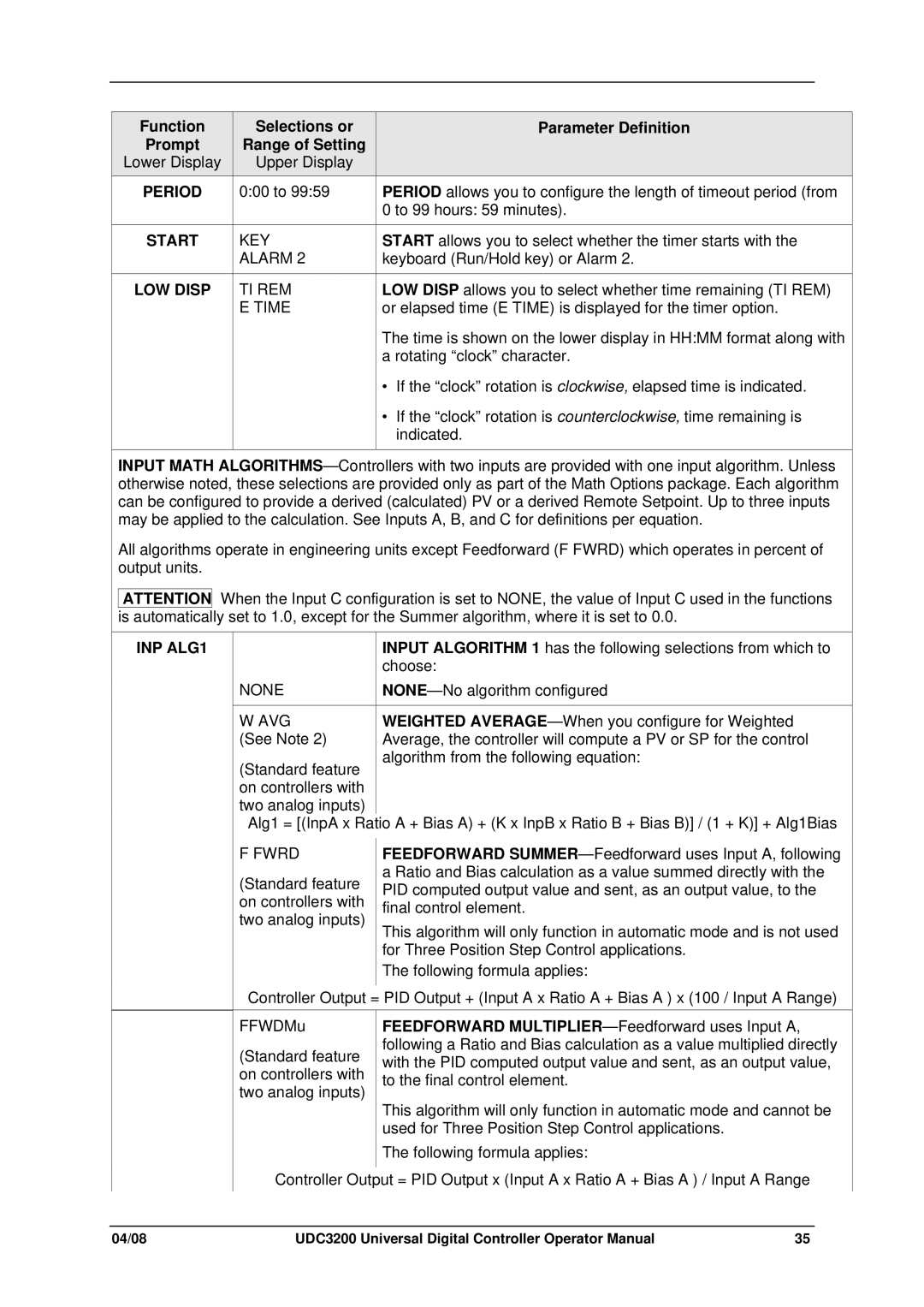
PERIOD | 0:00 to 99:59 |
|
|
START | KEY |
| ALARM 2 |
|
|
LOW DISP | TI REM |
| E TIME |
|
|
Parameter Definition
PERIOD allows you to configure the length of timeout period (from 0 to 99 hours: 59 minutes).
START allows you to select whether the timer starts with the keyboard (Run/Hold key) or Alarm 2.
LOW DISP allows you to select whether time remaining (TI REM) or elapsed time (E TIME) is displayed for the timer option.
The time is shown on the lower display in HH:MM format along with a rotating “clock” character.
•If the “clock” rotation is clockwise, elapsed time is indicated.
•If the “clock” rotation is counterclockwise, time remaining is indicated.
INPUT MATH
All algorithms operate in engineering units except Feedforward (F FWRD) which operates in percent of output units.
ATTENTION When the Input C configuration is set to NONE, the value of Input C used in the functions is automatically set to 1.0, except for the Summer algorithm, where it is set to 0.0.
INP ALG1
| INPUT ALGORITHM 1 has the following selections from which to |
| choose: |
NONE | |
|
|
W AVG | WEIGHTED |
(See Note 2) | Average, the controller will compute a PV or SP for the control |
(Standard feature | algorithm from the following equation: |
| |
on controllers with |
|
two analog inputs) |
|
Alg1 = [(InpA x Ratio A + Bias A) + (K x InpB x Ratio B + Bias B)] / (1 + K)] + Alg1Bias
F FWRD
(Standard feature on controllers with two analog inputs)
FEEDFORWARD
This algorithm will only function in automatic mode and is not used for Three Position Step Control applications.
The following formula applies:
Controller Output = PID Output + (Input A x Ratio A + Bias A ) x (100 / Input A Range)
FFWDMu
(Standard feature on controllers with two analog inputs)
FEEDFORWARD
This algorithm will only function in automatic mode and cannot be used for Three Position Step Control applications.
The following formula applies:
Controller Output = PID Output x (Input A x Ratio A + Bias A ) / Input A Range
04/08 | UDC3200 Universal Digital Controller Operator Manual | 35 |